

A study of grid artifacts formation and elimination in computed radiographic images
- PMID: 16763931
- PMCID: PMC3045157
- DOI: 10.1007/s10278-006-0630-8
A study of grid artifacts formation and elimination in computed radiographic images
Abstract
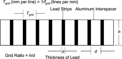
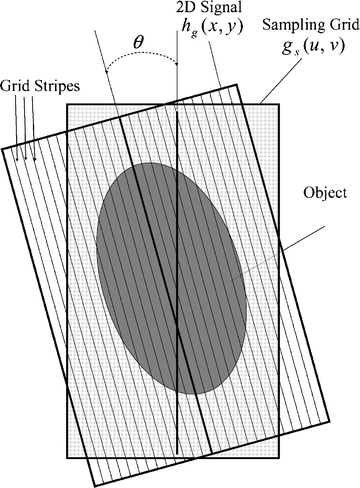
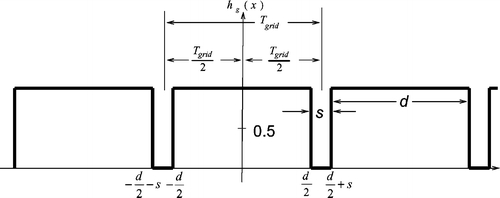
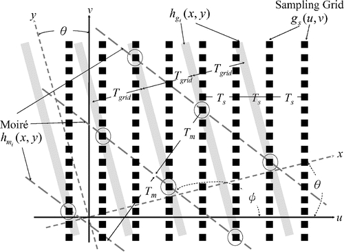
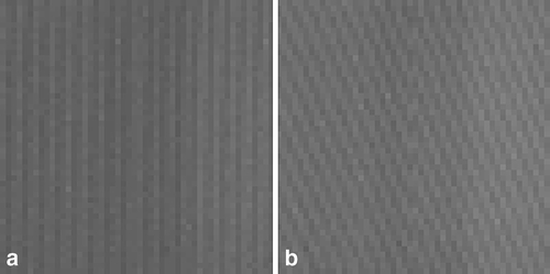
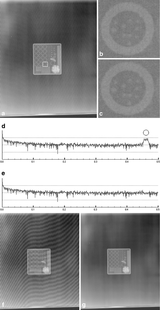
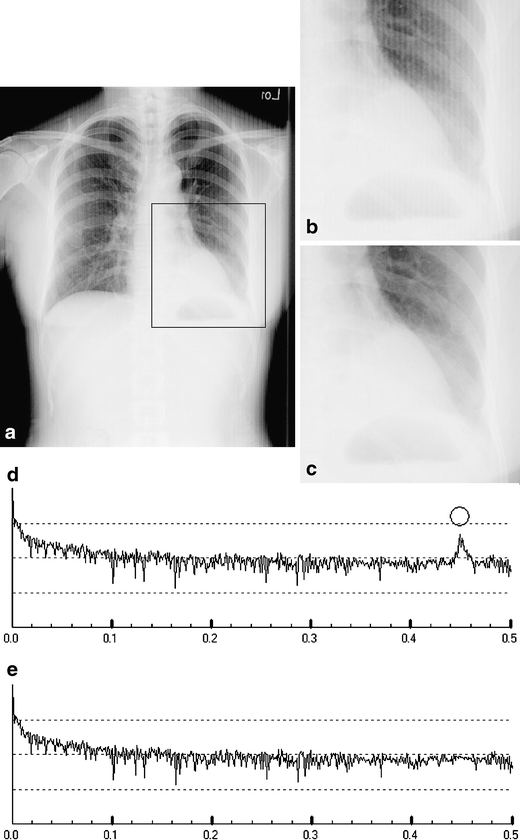
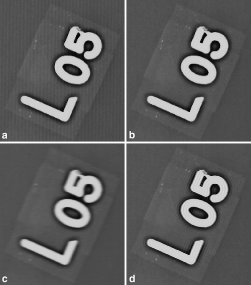
Computed radiography (CR) has many advantages such as filmless operations, efficiency, and convenience. Furthermore, it is easier to integrate with the picture archiving and communication systems. Another important advantage is that CR images generally have a wider dynamic range than conventional screen film. Unfortunately, grid artifacts and moiré pattern artifacts may be present in CR images. These artifacts become a more serious problem when viewing CR images on a computer monitor when a clinic grade monitor is not available. Images produced using a grid with higher frequency or a Potter--Bucky grid (i.e., a moving grid, Bucky for short) can reduce occurrence but cannot guarantee elimination of these artifacts [CR & PACS (2000); Detrick F (2001), pp 7-8]. In this paper, the formation of the artifacts is studied. We show that the grid artifacts occur in a narrow band of frequency in the frequency domain. The frequency can be determined, accurately located, and thus removed from the frequency domain. When comparing the results obtained from the proposed method against the results obtained using previous computer methods, we show that our method can achieve better image quality.
Figures
Similar articles
-
Acquisition of a single grid-based phase-contrast X-ray image using instantaneous frequency and noise filtering.Biomed Eng Online. 2022 Dec 27;21(1):92. doi: 10.1186/s12938-022-01061-z. Biomed Eng Online. 2022. PMID: 36575491 Free PMC article.
-
Image quality and dose comparison among screen-film, computed, and CT scanned projection radiography: applications to CT urography.Radiology. 2001 Nov;221(2):395-403. doi: 10.1148/radiol.2212000784. Radiology. 2001. PMID: 11687682
-
Enhanced visualization methods for computed radiography images.J Digit Imaging. 2006 Jun;19(2):187-96. doi: 10.1007/s10278-005-9246-7. J Digit Imaging. 2006. PMID: 16341634 Free PMC article.
-
Pediatric musculoskeletal computed radiography.Pediatr Radiol. 1997 Jul;27(7):563-75. doi: 10.1007/s002470050184. Pediatr Radiol. 1997. PMID: 9211947 Review.
-
Computed radiography image artifacts revisited.AJR Am J Roentgenol. 2011 Jan;196(1):W37-47. doi: 10.2214/AJR.10.5563. AJR Am J Roentgenol. 2011. PMID: 21178029 Review.
Cited by
-
Run length encoding based wavelet features for COVID-19 detection in X-rays.BJR Open. 2021 Feb 2;3(1):20200028. doi: 10.1259/bjro.20200028. eCollection 2021. BJR Open. 2021. PMID: 33718765 Free PMC article.
-
Design and evaluation of a grid reciprocation scheme for use in digital breast tomosynthesis.Proc SPIE Int Soc Opt Eng. 2016 Feb 27;9788:978805. doi: 10.1117/12.2216248. Epub 2016 Mar 29. Proc SPIE Int Soc Opt Eng. 2016. PMID: 28855746 Free PMC article.
-
Transmission characteristics of a two dimensional antiscatter grid prototype for CBCT.Med Phys. 2017 Aug;44(8):3952-3964. doi: 10.1002/mp.12346. Epub 2017 Jun 16. Med Phys. 2017. PMID: 28513847 Free PMC article.
-
Limitations of anti-scatter grids when used with high resolution image detectors.Proc SPIE Int Soc Opt Eng. 2014 Mar 19;9033:903362. doi: 10.1117/12.2043063. Proc SPIE Int Soc Opt Eng. 2014. PMID: 25309101 Free PMC article.
-
Evaluation of the microangiographic fluoroscope (MAF) using generalized system performance metrics.Med Phys. 2013 Mar;40(3):031915. doi: 10.1118/1.4792460. Med Phys. 2013. PMID: 23464330 Free PMC article.
References
-
- Cesar LJ, Schueler BA, Zink FE, Daly TR, Taubel JP, Jorgenson LL: Artifacts found in computed radiography. Br J Radiol 195-202, 2001 - PubMed
-
- Lee Wen-jeng, Tsao Bo-Shen, Ching Yu-Tai, Chen Shyh-Jye, Chang Chia-Hung, Chen Chien-Jung, Yen York, Lee Yuan-Ten: High Resolution Hand-held computer as a Portable PACS Terminal Using Wireless LAN and GPRS. EuroPACS 2002 Conference, Oulu, Finland
-
- Wang Jun, Huang HK: Film digitization aliasing artifacts caused by grid line patterns. IEEE Trans Med Imaging 375–385, 1994 - PubMed
-
- Barski LL, Wang X: Characterization, detection and suppression of stationary grids in digital projection radiography imagery. Proc SPIE 502-519, 1999
-
- Belykh IN, Cornelius CW: Antiscatter stationary grid artifacts automated detection and removal in projection radiography images. Proc SPIE 1162–1166, 2001
Publication types
MeSH terms
LinkOut - more resources
Full Text Sources
Medical
Miscellaneous
