. 2006 Jun 27;103(26):9873-8.
doi: 10.1073/pnas.0602249103. Epub 2006 Jun 15.

The Dam1 kinetochore complex harnesses microtubule dynamics to produce force and movement

Affiliations

The Dam1 kinetochore complex harnesses microtubule dynamics to produce force and movement

Charles L Asbury et al. Proc Natl Acad Sci U S A. .

Abstract

Kinetochores remain attached to microtubule (MT) tips during mitosis even as the tips assemble and disassemble under their grip, allowing filament dynamics to produce force and move chromosomes. The specific proteins that mediate tip attachment are uncertain, and the mechanism of MT-dependent force production is unknown. Recent work suggests that the Dam1 complex, an essential component of kinetochores in yeast, may contribute directly to kinetochore-MT attachment and force production, perhaps by forming a sliding ring encircling the MT. To test these hypotheses, we developed an in vitro motility assay where beads coated with pure recombinant Dam1 complex were bound to the tips of individual dynamic MTs. The Dam1-coated beads remained tip-bound and underwent assembly- and disassembly-driven movement over approximately 3 microm, comparable to chromosome displacements in vivo. Dam1-based attachments to assembling tips were robust, supporting 0.5-3 pN of tension applied with a feedback-controlled optical trap as the MTs lengthened approximately 1 microm. The attachments also harnessed energy from MT disassembly to generate movement against tension. Reversing the direction of force (i.e., switching to compressive force) caused the attachments to disengage the tip and slide over the filament, but sliding was blocked by areas where the MT was anchored to a coverslip, consistent with a coupling structure encircling the filament. Our findings demonstrate how the Dam1 complex may contribute directly to MT-driven chromosome movement.


Conflict of interest statement

Conflict of interest statement: No conflicts declared.

Figures
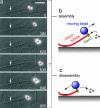
Fig. 1.
Fig. 1.
Dam1 couples cargo to the tips of assembling and disassembling MTs. (a) Selected frames from a movie (Movie 1) in which movement of a Dam1-coated bead is driven by MT assembly (0–835 s) and disassembly (835–850 s). Approximate locations for the coverslip-anchored portion of the MT seed (arrows) and the bead center (plus signs) are indicated. Elapsed times are in seconds. (Scale bar, 5 μm.) (b and c) Schematic diagrams of the Dam1 bead motility assay. During assembly (b), the MT grows slowly by addition of tubulin subunits to the tip. During shortening (c), tubulin subunits are rapidly lost from the tip. During both phases, Dam1-based linkages remain tip-bound.
Fig. 2.
Fig. 2.
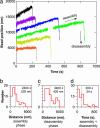
MTs drive movement of Dam1-based linkages over several micrometers. (a) Records of bead position versus time measured without applied force showing slow assembly-driven movement followed by rapid disassembly-driven movement. Increasing position represents movement away from the anchored portion of the MT. For clarity, each record is offset vertically by an arbitrary amount. (bd) Histograms of bead displacement during MT assembly (b), bead displacement during disassembly (c), and total duration (including both assembly and disassembly phases) of MT-driven movement (d) for a population of beads. Dotted vertical lines indicate the mean value for each histogram. These data were recorded at a tubulin concentration of 17 μM.
Fig. 3.
Fig. 3.
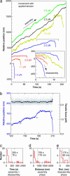
Dam1-based linkages remain tip-attached even when tension is applied. (a) Records of bead position versus time during continuous application of tensile load by using a feedback-controlled optical trap. Increasing position represents assembly-coupled movement in the direction of applied force, away from the anchored portion of the MT (e.g., green and black traces and blue trace at <200 s). Some records terminate with episodes of disassembly-driven movement against the load (e.g., blue trace at 200–210 s), expanded views of which are shown in Inset. Records are offset vertically (and horizontally in Inset) for clarity. (b) Expanded view of the bracketed portion of the record in a showing transition from assembly- to disassembly-driven movement (blue trace). Arrows mark positions where the bead paused during movement. The measured bead-trap separation is shown in the upper plot (black trace; scale at right) after converting to force by multiplying by the trap stiffness. The gray dots show raw data, and the black trace shows the same data after smoothing with a 500-ms sliding boxcar average. (ce) Histograms of total attached time (including both assembly and disassembly phases) (c), distance moved during assembly (d), and distance moved during disassembly (e) for tip-attached beads moving under 0.5–3 pN of tension. Dotted vertical lines indicate the means for each histogram. Tubulin concentration was 10 μM.
Fig. 4.
Fig. 4.
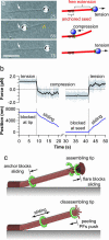
Dam1-based couplers slide over the MT lattice without detaching, and both the growing tip and the coverslip-anchored portion of the MT present barriers to sliding. (a) Selected frames from a movie are shown (Movie 6), beginning with a tip-attached bead under tension (25 s). Reversing the direction of load (i.e., switching to compression) causes the bead to disengage the tip (denoted by the yellow chevron) and slide until it reaches the seed (white arrow), where sliding halts (65 s). Reversing the load again (i.e., reapplying tension) causes the bead to slide back and reengage the tip (75 s). (Scale bar, 5 μm.) (b) Beads located at the growing tip or the anchored seed respond asymmetrically to force: The same magnitude of force that is insufficient to slide them past the barrier, when reversed, immediately causes the bead to slide back away from the barrier. The lower plot shows bead position versus time, and the upper plot shows bead-trap separation after conversion to force by multiplying by the trap stiffness. Gray dots show raw data; black trace shows same data after smoothing with a 500-ms window. Dotted vertical lines mark the time when force was reversed. (c) Ring model for Dam1-based attachment and movement. In this view, between 10 and 16 Dam1 complexes (19, 27) oligomerize into a ring encircling the filament that is large enough to slide over the lattice (arrows) but too small to slide past areas where the filament is widened. Such a ring would be topologically prevented from sliding past the anchored segment of the MT (dotted line at left), as we observed. Growing tips also blocked sliding, perhaps because of the flared protofilament sheets that are thought to occur at assembling tips (38, 39). Protofilaments (PFs) curl and peel away from the main filament during disassembly (36, 37) and could push continuously against a Dam1 ring to drive movement in the direction of shortening. An alternative model in which coupling is provided by a disordered collection of MT-binding proteins is also consistent with our observations (see Discussion).

References

    1. Gadde S., Heald R. Curr. Biol. 2004;14:R797–R805. - PubMed
    1. Inoue S., Salmon E. D. Mol. Biol. Cell. 1995;6:1619–1640. - PMC - PubMed
    1. McIntosh J. R., Grishchuk E. L., West R. R. Annu. Rev. Cell Dev. Biol. 2002;18:193–219. - PubMed
    1. Howard J. Annu. Rev. Physiol. 1996;58:703–729. - PubMed
    1. Vale R. D. Cell. 2003;112:467–480. - PubMed

Publication types

MeSH terms

Substances