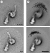
Dynamic allostery of protein alpha helical coiled-coils
- PMID: 16849225
- PMCID: PMC1618481
- DOI: 10.1098/rsif.2005.0068
Dynamic allostery of protein alpha helical coiled-coils
Abstract
Alpha helical coiled-coils appear in many important allosteric proteins such as the dynein molecular motor and bacteria chemotaxis transmembrane receptors. As a mechanism for transmitting the information of ligand binding to a distant site across an allosteric protein, an alternative to conformational change in the mean static structure is an induced change in the pattern of the internal dynamics of the protein. We explore how ligand binding may change the intramolecular vibrational free energy of a coiled-coil, using parameterized coarse-grained models, treating the case of dynein in detail. The models predict that coupling of slide, bend and twist modes of the coiled-coil transmits an allosteric free energy of approximately 2kBT, consistent with experimental results. A further prediction is a quantitative increase in the effective stiffness of the coiled-coil without any change in inherent flexibility of the individual helices. The model provides a possible and experimentally testable mechanism for transmission of information through the alpha helical coiled-coil of dynein.
Figures


Similar articles
-
Model for the unidirectional motion of a dynein molecule.Phys Rev E Stat Nonlin Soft Matter Phys. 2008 May;77(5 Pt 1):051916. doi: 10.1103/PhysRevE.77.051916. Epub 2008 May 19. Phys Rev E Stat Nonlin Soft Matter Phys. 2008. PMID: 18643111
-
Structure of the entire stalk region of the Dynein motor domain.J Mol Biol. 2014 Sep 23;426(19):3232-3245. doi: 10.1016/j.jmb.2014.06.023. Epub 2014 Jul 21. J Mol Biol. 2014. PMID: 25058684
-
Clockwise translocation of microtubules by flagellar inner-arm dyneins in vitro.Biophys J. 2008 May 15;94(10):4014-9. doi: 10.1529/biophysj.107.123083. Epub 2008 Jan 30. Biophys J. 2008. PMID: 18234824 Free PMC article.
-
Communication between the AAA+ ring and microtubule-binding domain of dynein.Biochem Cell Biol. 2010 Feb;88(1):15-21. doi: 10.1139/o09-127. Biochem Cell Biol. 2010. PMID: 20130675 Free PMC article. Review.
-
Coiled coils and SAH domains in cytoskeletal molecular motors.Biochem Soc Trans. 2011 Oct;39(5):1142-8. doi: 10.1042/BST0391142. Biochem Soc Trans. 2011. PMID: 21936779 Review.
Cited by
-
Allosteric Binding Sites of the SARS-CoV-2 Main Protease: Potential Targets for Broad-Spectrum Anti-Coronavirus Agents.Drug Des Devel Ther. 2022 Aug 2;16:2463-2478. doi: 10.2147/DDDT.S370574. eCollection 2022. Drug Des Devel Ther. 2022. PMID: 35941927 Free PMC article. Review.
-
Modulation of global low-frequency motions underlies allosteric regulation: demonstration in CRP/FNR family transcription factors.PLoS Biol. 2013 Sep;11(9):e1001651. doi: 10.1371/journal.pbio.1001651. Epub 2013 Sep 10. PLoS Biol. 2013. PMID: 24058293 Free PMC article.
-
Allosteric conformational change cascade in cytoplasmic dynein revealed by structure-based molecular simulations.PLoS Comput Biol. 2017 Sep 11;13(9):e1005748. doi: 10.1371/journal.pcbi.1005748. eCollection 2017 Sep. PLoS Comput Biol. 2017. PMID: 28892477 Free PMC article.
-
Coupling of global and local vibrational modes in dynamic allostery of proteins.Biophys J. 2006 Sep 15;91(6):2055-62. doi: 10.1529/biophysj.106.082180. Epub 2006 Jun 23. Biophys J. 2006. PMID: 16798805 Free PMC article.
-
Structural insight into photoactivation of an adenylate cyclase from a photosynthetic cyanobacterium.Proc Natl Acad Sci U S A. 2016 Jun 14;113(24):6659-64. doi: 10.1073/pnas.1517520113. Epub 2016 May 31. Proc Natl Acad Sci U S A. 2016. PMID: 27247413 Free PMC article.
References
-
- Boal D. Cambridge University Press; Cambridge: 2002. Mechanics of the cell.
-
- Burgess S.A, Walker M.L, Sakakibara H, Knight P.J, Oiwa K. dynein structure and power stroke. Nature. 2003;421:715–718. doi:10.1038/nature01377 - DOI - PubMed
-
- Burgess S, Walker M, Sakakibara H, Oiwa K, Knight P. The structure of dynein-c by negative stain electron microscopy. J. Struct. Biol. 2004a;146:205–216. doi:10.1016/j.jsb.2003.10.005 - DOI - PubMed
-
- Burgess S.A, Walker M.L, Thirumurugan K, Trinick J, Knight P.J. Use of negative stain and single-particle image processing to explore dynamic properties of flexible macromolecules. J. Struct. Biol. 2004b;147:247–258. doi:10.1016/j.jsb.2004.04.004 - DOI - PubMed
-
- Case D, et al. University of California; San Francisco: 2004. AMBER 8.
Publication types
MeSH terms
Substances
LinkOut - more resources
Full Text Sources
Research Materials

