

An inversion formula for the exponential radon transform in spatial domain with variable focal-length fan-beam collimation geometry
- PMID: 16878581
- PMCID: PMC1553217
- DOI: 10.1118/1.2170596
An inversion formula for the exponential radon transform in spatial domain with variable focal-length fan-beam collimation geometry
Abstract
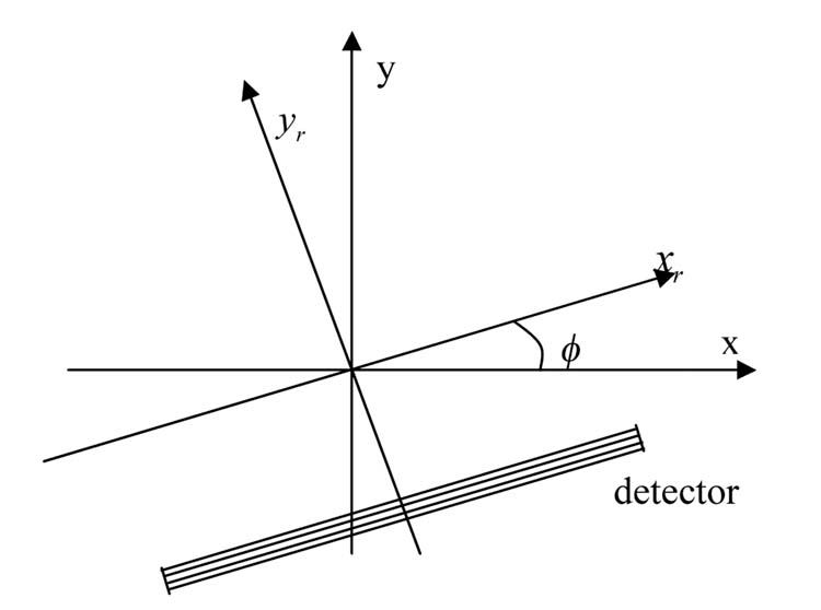
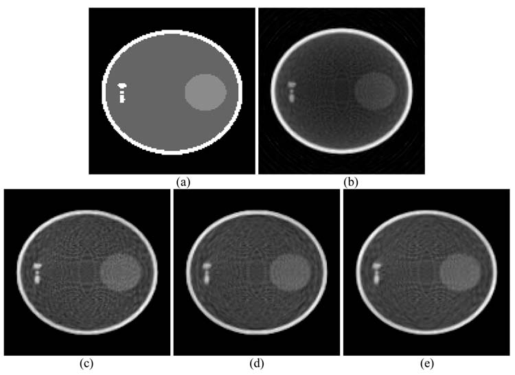
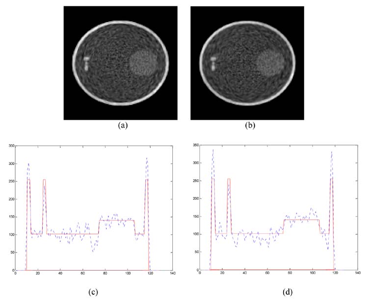
Inverting the exponential Radon transform has a potential use for SPECT (single photon emission computed tomography) imaging in cases where a uniform attenuation can be approximated, such as in brain and abdominal imaging. Tretiak and Metz derived in the frequency domain an explicit inversion formula for the exponential Radon transform in two dimensions for parallel-beam collimator geometry. Progress has been made to extend the inversion formula for fan-beam and varying focal-length fan-beam (VFF) collimator geometries. These previous fan-beam and VFF inversion formulas require a spatially variant filtering operation, which complicates the implementation and imposes a heavy computing burden. In this paper, we present an explicit inversion formula, in which a spatially invariant filter is involved. The formula is derived and implemented in the spatial domain for VFF geometry (where parallel-beam and fan-beam geometries are two special cases). Phantom simulations mimicking SPECT studies demonstrate its accuracy in reconstructing the phantom images and efficiency in computation for the considered collimator geometries.
Figures


Similar articles
-
A SPECT reconstruction method for extending parallel to non-parallel geometries.Phys Med Biol. 2010 Mar 21;55(6):1631-41. doi: 10.1088/0031-9155/55/6/007. Epub 2010 Feb 24. Phys Med Biol. 2010. PMID: 20182002
-
A unified reconstruction framework for both parallel-beam and variable focal-length fan-beam collimators by a Cormack-type inversion of exponential radon transform.IEEE Trans Med Imaging. 1999 Jan;18(1):59-65. doi: 10.1109/42.750255. IEEE Trans Med Imaging. 1999. PMID: 10193697
-
An efficient reconstruction method for nonuniform attenuation compensation in nonparallel beam geometries based on Novikov's explicit inversion formula.IEEE Trans Med Imaging. 2005 Oct;24(10):1357-68. doi: 10.1109/TMI.2005.857026. IEEE Trans Med Imaging. 2005. PMID: 16229421 Free PMC article.
-
Exact fan-beam and 4pi-acquisition cone-beam SPECT algorithms with uniform attenuation correction.Med Phys. 2005 Nov;32(11):3440-7. doi: 10.1118/1.2068907. Med Phys. 2005. PMID: 16372416
-
Application of convergent-beam collimation and simultaneous transmission emission tomography to cardiac single-photon emission computed tomography.Semin Nucl Med. 1994 Jan;24(1):17-37. doi: 10.1016/s0001-2998(05)80247-8. Semin Nucl Med. 1994. PMID: 8122126 Review.
References
-
- Gullberg GT. University of California at Berkeley; CA: 1979.
-
- Arbuzov E, Bukhgeim A, Kazantsev S. Two-dimensional tomography problems and the theory of A-analytic Functions. Siberian Advances in Mathematics. 1998;8:1–20.
-
- Novikov RG. An inversion formula for the attenuated X-ray transformation. Ark. Math. 2002;40:145–167. Preprint, May of 2000.
-
- Shepp LA, Logan B B. The Fourier reconstruction of a head section. IEEE Trans Nucl. Science. 1974;21:21–43.
-
- Natterer F. Inversion of the attenuated Radon transform. Inverse Problems. 2001;17:113–119.
Publication types
MeSH terms
Substances
Grants and funding
LinkOut - more resources
Full Text Sources
Medical
