. 2006 Aug 22;103(34):12668-71.
doi: 10.1073/pnas.0605396103. Epub 2006 Aug 2.

Magnetic resonance imaging with an optical atomic magnetometer

Affiliations

Magnetic resonance imaging with an optical atomic magnetometer

Shoujun Xu et al. Proc Natl Acad Sci U S A. .

Abstract

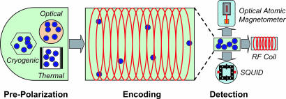
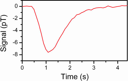
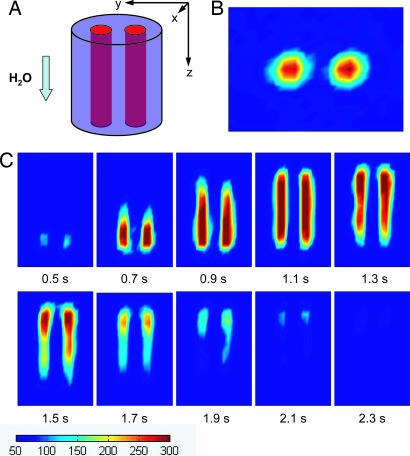
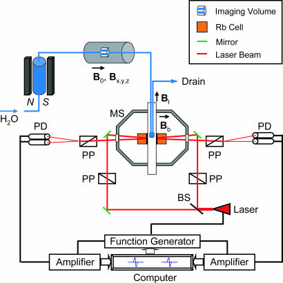
We report an approach for the detection of magnetic resonance imaging without superconducting magnets and cryogenics: optical atomic magnetometry. This technique possesses a high sensitivity independent of the strength of the static magnetic field, extending the applicability of magnetic resonance imaging to low magnetic fields and eliminating imaging artifacts associated with high fields. By coupling with a remote-detection scheme, thereby improving the filling factor of the sample, we obtained time-resolved flow images of water with a temporal resolution of 0.1 s and spatial resolutions of 1.6 mm perpendicular to the flow and 4.5 mm along the flow. Potentially inexpensive, compact, and mobile, our technique provides a viable alternative for MRI detection with substantially enhanced sensitivity and time resolution for various situations where traditional MRI is not optimal.


Conflict of interest statement

Conflict of interest statement: No conflicts declared.

Figures

Fig. 1.
Fig. 1.
Various prepolarization and detection methods for MRI in combination with remote detection. To overcome the limited nuclear polarization in low magnetic fields, prepolarization methods can be applied, including spin-exchange optical pumping by lasers, polarization by cryogenics, and thermal polarization by permanent magnets. In the encoding stage, excitation pulses and gradient pulses are applied to store spatial information as nuclear spin magnetization. For detection, the methods of optical atomic magnetometer, radio frequency (RF) coil, and superconducting quantum interference device (SQUID) are shown.
Fig. 2.
Fig. 2.
Flow profile of water measured by magnetization inversion by a single π pulse.
Fig. 3.
Fig. 3.
Magnetic resonance images. (A) The encoding volume. The two channels are 3.2 mm in diameter and 25 mm long each, with a center-to-center spacing of 5.1 mm. (B) Image of the cross-section of the encoding volume perpendicular to the flow (xy plane) at t = 1.1 s. (C) Time-resolved images in the yz plane. Measurements were obtained with a time interval of 0.1 s. All of the images are color-mapped at the same scale, as indicated below the images. The total experimental time for these flow images is 12 h, which is dominated by the waiting time between measurements to allow the sample from the previous measurement cycle to clear the system. The overall time will be reduced to minutes with shorter travel distances.
Fig. 4.
Fig. 4.
Schematic of the experimental setup. The magnetometer consists of two rubidium (87Rb) vapor cells forming a first-order gradiometer. The cells are cubic, with a 1-cm side length, and maintained at 43°C. The beam from a single laser (whose wavelength is resonant with the rubidium D1 transition) is split equally into two, one for each cell. For each arm of the gradiometer, polarizing and analyzing prisms are oriented at 45° to each other to detect optical rotation occurring in the vapor cell. The intrinsic resonance linewidth is ≈5 Hz. A piercing solenoid provides a 0.05-mT leading field (Bl). The geometry is such that the rubidium atoms are not subject to this field. A bias field of 70 nT (Bb) gives a resonance frequency of ≈1,000 Hz for the modulation of the laser when no sample is introduced. The magnetometer measures the magnetic field change along the direction of the bias field. The magnetized sample in the detection region produces magnetic fields of opposite direction in the two cells. The frequency of magneto-optical resonance on one arm of the gradiometer is fed back to the laser modulation to maintain this arm on resonance. Thus the optical rotation in the other cell represents the difference field between the two cells, equal to twice the magnetic field produced by the sample. N, north pole; S, south pole; PD, photo diode; PP, polarization prism; MS, magnetic shield; BS, beam splitter.
Fig. 5.
Fig. 5.
Pulse sequences used in the experiments. (A) A π pulse used to invert the spins for measuring the flow profile. The pulse duration is 116 μs. The detection timing of the magnetometer is relative to the π pulse. (B) Phase-encoding pulse sequence for magnetic resonance imaging. The pulse duration is 58 μs for the π/2 pulses and 1.2 ms for the phase-encoding gradient pulses (GPE). The gradient step sizes were 0.3, 0.22, and 0.1 G/cm, for axes x, y, and z (flow direction), respectively. The number of steps are 10, 14, and 10 for x, y, and z, respectively.

Comment in

  • MRI without the magnet.
    Raftery D. Raftery D. Proc Natl Acad Sci U S A. 2006 Aug 22;103(34):12657-8. doi: 10.1073/pnas.0605625103. Epub 2006 Aug 15. Proc Natl Acad Sci U S A. 2006. PMID: 16912110 Free PMC article. No abstract available.

References

    1. Callaghan P. T. Principles of Nuclear Magnetic Resonance Microscopy. New York: Clarendon; 1991.
    1. Blümich B. NMR Imaging of Materials. Oxford: Oxford Univ. Press; 2000.
    1. Hoult D. I., Richards R. E. J. Magn. Reson. 1976;24:71–85. - PubMed
    1. Kleiner R., Koelle D., Ludwig F., Clarke J. Proc. IEEE; 2004. pp. 1534–1548.
    1. Oukhanski N., Stolz R., Zakosarenko V., Meyer H. G. Physica C. 2002;368:166–170.

Publication types

MeSH terms