. 2006 Sep;18(9):2145-56.
doi: 10.1105/tpc.106.043042. Epub 2006 Aug 11.

Visualizing plant development and gene expression in three dimensions using optical projection tomography

Affiliations

Visualizing plant development and gene expression in three dimensions using optical projection tomography

Karen Lee et al. Plant Cell. 2006 Sep.

Abstract

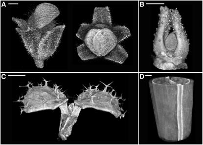
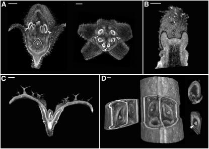
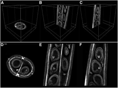
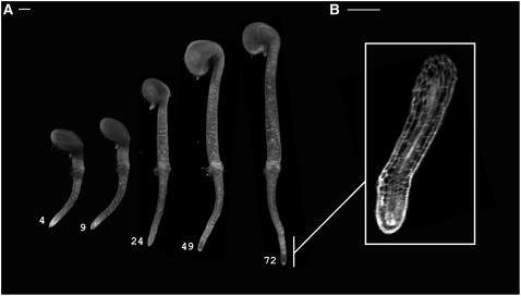
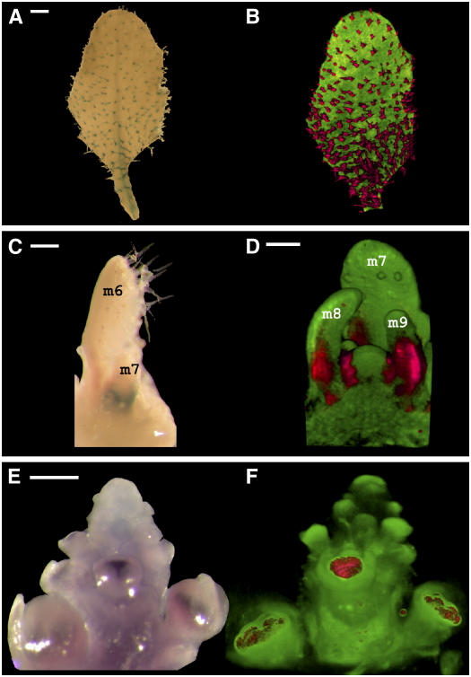
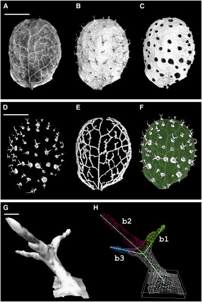
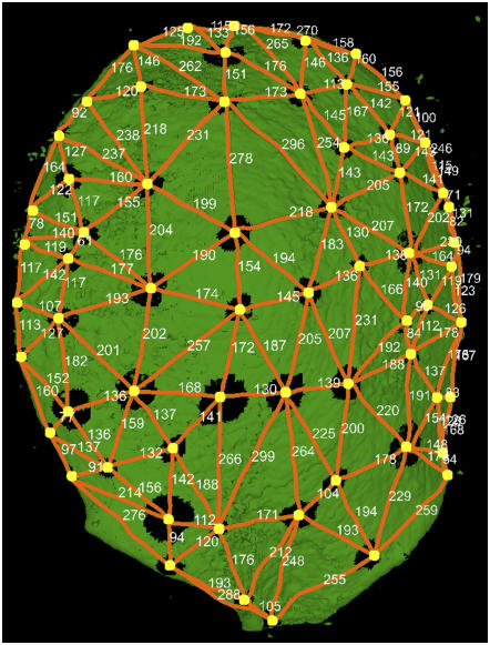
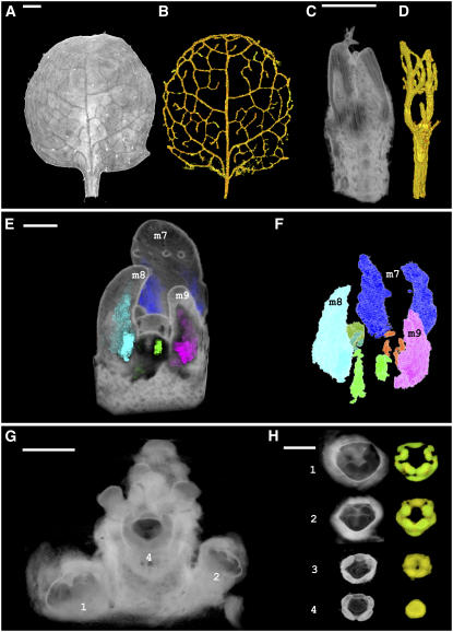
A deeper understanding of the mechanisms that underlie plant growth and development requires quantitative data on three-dimensional (3D) morphology and gene activity at a variety of stages and scales. To address this, we have explored the use of optical projection tomography (OPT) as a method for capturing 3D data from plant specimens. We show that OPT can be conveniently applied to a wide variety of plant material at a range of scales, including seedlings, leaves, flowers, roots, seeds, embryos, and meristems. At the highest resolution, large individual cells can be seen in the context of the surrounding plant structure. For naturally semitransparent structures, such as roots, live 3D imaging using OPT is also possible. 3D domains of gene expression can be visualized using either marker genes, such as beta-glucuronidase, or more directly by whole-mount in situ hybridization. We also describe tools and software that allow the 3D data to be readily quantified and visualized interactively in different ways.


Figures

Figure 1.
Figure 1.
OPT Data Reconstructed and Displayed as Volumes. (A) OPT volume views of an Antirrhinum flower. The image is based on a combination of transmission and fluorescence OPT (Leica TXR filter and GFP1 filters). Bar = 525 μm. (B) Antirrhinum vegetative meristem imaged by fluorescence OPT (GFP1 filter). Bar = 85 μm. (C) First true leaves of an Arabidopsis seedling showing trichome cells on the adaxial leaf surface (cotyledons removed). The image was taken with fluorescence OPT (GFP1 filter). Bar = 285 μm. (D) Part of an Arabidopsis silique imaged by fluorescence OPT (TXR filter). Bar = 42 μm.
Figure 2.
Figure 2.
Clipping to Reveal Internal Morphology. (A) Virtual dissection using clipping planes of the Antirrhinum flower shown in Figure 1A reveals internal floral structures such as anther lobes (arrowheads) and the ovary at the base of the carpel (asterisk). Pollen is more autofluorescent than the surrounding tissues, making the anthers appear brighter. Bars = 200 μm (left) and 365 μm (right). (B) Clipping plane through the center of the Antirrhinum shoot apical meristem. Bar = 55 μm. (C) An Arabidopsis seedling clipped to display vasculature. Vasculature is more autofluorescent than the surrounding tissue, making it appear brighter. Bar = 100 μm. (D) An Arabidopsis silique (from Figure 1D) clipped to reveal internal structure. A piece was removed using three clipping planes to show the seeds developing within. The removed piece is shown at left. Individual seeds were also dissected out using six clipping planes to display the heart-stage embryo (arrowhead) and endosperm within (two examples shown at right). Bar = 35 μm.
Figure 3.
Figure 3.
Virtual Sectioning of an Arabidopsis Silique. (A) to (C) Orthogonal sections in their original orientations: xy section (A); zx section (B); and yz section (C). (D) to (F) Orthogonal sections oriented parallel to the viewing plane: xy section showing two valves (v) surrounding the developing seeds and the septum (arrowhead) (D); zx section (E); and yz section with heart-stage embryos labeled (asterisks) (F). Bar = 32 μm.
Figure 4.
Figure 4.
Live OPT Imaging. (A) Volume views of an Arabidopsis seedling growing within the OPT device. A series of OPT scans in water collected at 4, 9, 24, 49, and 72 h after the start of the experiment is shown (transmission OPT channel). Bar = 100 μm. (B) yz section view of the same root as in (A) captured at higher magnification (8×) collected 30 h after the start of the experiment. Bar = 60 μm.
Figure 5.
Figure 5.
Visualization of Gene Expression in 3D. (A) GL2:GUS Arabidopsis leaf showing GUS staining in the trichomes (metamer 5; 13 d from sowing). Bar = 250 μm. (B) Combined volume view of the leaf shown in (A). Transmission OPT highlights GUS-stained trichomes, shown in red. Fluorescence OPT highlights the remaining leaf tissue, shown in green (GFP1 filter). The two channels were combined and displayed in the same 3D space. Data were collected with OPT Scanner 3001. (C) LFY:GUS Arabidopsis seedling, after leaf removal and staining to reveal GUS activity (metamers 1 to 5 were removed; 8 d from sowing). Metamers 6 and 7 (m6 and m7) are labeled. Bar = 170 μm. (D) Combined volume view of the seedling shown in (C). The view was clipped to remove metamer 6 and reveal LFY:GUS staining (red) in emerging leaves (m8 and m9). Signal is also seen in the flanks of the shoot apical meristem. Red signal is from transmission OPT, and green signal is from fluorescence OPT (GFP1 filter). Bar = 45 μm. (E) DEF expression in stamen and petal primordia of developing flowers in an Antirrhinum inflorescence meristem revealed by whole-mount RNA in situ hybridization. Bar = 350 μm. (F) Volume view of the Antirrhinum inflorescence shown in (E) with DEF expression highlighted in red and the surrounding tissue in green. This image was obtained by transmission OPT, with a threshold used to distinguish signal from background.
Figure 6.
Figure 6.
Extraction of Morphological Landmarks. (A) OPT fluorescence volume view of an Arabidopsis leaf (metamer 3; 12 d from sowing) (GFP1 filter). Although the volume data contain information about trichomes and venation pattern, it cannot be readily seen with this view. (B) Surface extracted from the same data used for (A). Trichomes are now clearly visible on the leaf surface. (C) to (H) Using information from (A) and (B), it is possible to retrieve lamina and trichomes separately. Each component is surface rendered for clearer visualization. (C) Leaf lamina without trichomes. (D) Trichomes without lamina. (E) Veins alone. (F) Combined lamina, trichomes, and veins. (G) Surface rendering of a single trichome. (H) Main axes of the trichome shown in (G) with angles computed between each branch (b1 to b2, 89°; b2 to b3, 101°; and b3 to b1, 100°). Bars = 1140 μm in (A) to (F) and 40 μm (G) and (H).
Figure 7.
Figure 7.
Trichome Distribution Map. Extracted trichome pattern for the leaf shown in Figure 6A. The trichome bases were retrieved (yellow dots), and their separation along the leaf surface is indicated (orange lines). Distances were computed along the 3D surface of the leaf (see Figure 6B) in micrometers. Distances between trichome bases ranged from 54 to 299 μm, with a mean distance of 164 μm.
Figure 8.
Figure 8.
Extraction of Gene Expression Patterns from 3D Data Sets. (A) OPT volume view of a mature ATHB8:GUS Arabidopsis leaf stained to reveal GUS activity (metamer 2; 9 d from sowing). Combined transmission and fluorescent (GFP1) OPT channels were used. Bar = 200 μm. (B) GUS signal extracted using semiautomatic segmentation tools revealing the expression of ATHB8:GUS in veins. (C) OPT volume view of a young ATHB8:GUS dissected seedling (metamers 2 and 3; 4 d from sowing). Combined transmission and fluorescent (GFP1) channels were used. Cotyledons were removed and first true leaves are visible. Bar = 60 μm. (D) ATHB8 venation pattern extracted from (C). (E) OPT volume view of a LFY:GUS Arabidopsis meristem with expression domains highlighted. Gene expression was segmented as separate domains for each metamer and color-coded accordingly. Bar = 45 μm. (F) Domains shown in (E) displayed without surrounding tissues. LFY:GUS staining situated deeper within the volume is revealed. Color-coding is as follows: m7, blue; m8, turquoise; m9, pink; m10, dark green; m11, bright green; m12, orange. (G) OPT volume view of DEF expression in an Antirrhinum inflorescence. Flower buds are labeled consecutively, with flower 1 being the most mature in this series. Flowers are arranged with spiral phyllotaxy; flower 3 being occluded by flower 4 in this view. Bar = 350 μm. (H) Flowers from (G) were clipped and segmented, with intense DEF expression color-coded in green and weaker expression displayed in yellow. Flower 1, late stage 5 (without sepals). DEF is expressed in petal and stamen primordia. Flower 2, mid stage 5. DEF is strongly expressed in emerging petal and stamen primordia. Flower 3, early stage 5. DEF expression is in the ring of the emerging petal and stamen primordia. Flower 4, stage 4. DEF is expressed in the area where petals and stamens will later develop. Bar = 350 μm.

References

    1. Baldock, R.A., et al. (2003). EMAP and EMAGE: A framework for understanding spatially organized data. Neuroinformatics 1 309–325. - PubMed
    1. Blazquez, M.A., Soowal, L.N., Lee, I., and Weigel, D. (1997). LEAFY expression and flower initiation in Arabidopsis. Development 124 3835–3844. - PubMed
    1. Blythe, D. (1998). Advanced Graphics Programming Techniques Using OpenGL. SIGGRAPH 1998 Course. (New York: ACM Press).
    1. Bryson-Richardson, R.J., and Currie, P.D. (2004). Optical projection tomography for spatio-temporal analysis in the zebrafish. Methods Cell Biol. 76 37–50. - PubMed
    1. Coen, E.S., Romero, J.M., Doyle, S., Elliott, R., Murphy, G., and Carpenter, R. (1990). Floricaula: A homeotic gene required for flower development in Antirrhinum majus. Cell 63 1311–1322. - PubMed

Publication types

MeSH terms