. 2006 Sep 12;103(37):13618-23.
doi: 10.1073/pnas.0604122103. Epub 2006 Sep 1.

A microrotary motor powered by bacteria

Affiliations

A microrotary motor powered by bacteria

Yuichi Hiratsuka et al. Proc Natl Acad Sci U S A. .

Abstract

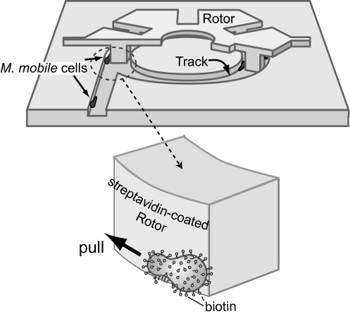
Biological molecular motors have a number of unique advantages over artificial motors, including efficient conversion of chemical energy into mechanical work and the potential for self-assembly into larger structures, as is seen in muscle sarcomeres and bacterial and eukaryotic flagella. The development of an appropriate interface between such biological materials and synthetic devices should enable us to realize useful hybrid micromachines. Here we describe a microrotary motor composed of a 20-mum-diameter silicon dioxide rotor driven on a silicon track by the gliding bacterium Mycoplasma mobile. This motor is fueled by glucose and inherits some of the properties normally attributed to living systems.


Conflict of interest statement

Conflict of interest statement: No conflicts declared.

Figures

Fig. 1.
Fig. 1.
Schematic illustrations of a microrotary motor driven by the gliding bacterium M. mobile. The microrotary motor consists of three parts, an Si circular track, an SiO2 rotor whose protrusions just fit into the groove of the track, and living cells of M. mobile that circle unidirectionally within the track. Unidirectional circling of the M. mobile cells is achieved by asymmetric introduction of the cells into the circular track along the track walls (19). The rotor is docked onto the track and binds to the circling M. mobile cells by biotin–streptavidin interactions. As a result, the rotor is pulled by the cells and rotates in one direction.
Fig. 2.
Fig. 2.
Fabrication processes of the microtrack (A) and the rotor (B). See Materials and Methods for details.
Fig. 3.
Fig. 3.
Scanning electron micrographs of the Si track (A–D) and the SiO2 rotor (E and F). (A) Overview of the track. When the M. mobile cells were settled onto the substrate, most attached within the square-shaped central depression (60 × 60 μm) created by Si etching and coated with fetuin molecules. A cell moving around in the square would eventually reach a side wall and begin to move along it until it was introduced into a circular track. (B) Enlarged image of the circular track. A straight track extended from the square area is asymmetrically connected to the circular track. A cell moving from the straight track enters the circular track and circles in a clockwise direction, jumping the gap formed by the straight track, guided by the sharp tip. (C) Tilted view of the circular track. The track was steeply carved by anisotropic etching with reactive ion. The depth of the etching was ≈500–600 nm. (D) Two cells are gliding along the side wall of the track. (Scale bar, 1 μm.) (E) Hexagonal microrotors during the process of fabrication (top view). Rotors are tethered to the Si base by two thin bridges designed to break upon sonication, releasing the rotors. (F) Rotors have protrusions that fit the circular grooves shown in A–C (tilted view). The heights of the protrusions are ≈1.4–1.5 μm.
Fig. 4.
Fig. 4.
Image of a rotor docked on the track and examples of the rotation of a rotor driven by the bacteria. (A) Scanning electron micrograph of a rotor docked onto a circular groove after placement using a micromanipulator. (Scale bar, 5 μm.) (B) Time-lapse photomicrographs of a rotating rotor taken at 5-s intervals. A portion of the rotor was pseudocolored in cyan to enable tracking. This rotor continuously rotated ≈60 degrees in 5 s (2.0 rpm). (C) Rotational speed of individual rotors. The rotational angles of continuously rotating rotors were measured from images captured at 0.5-s intervals and plotted against time. The traces marked a, b, c, and d correspond to the rotors shown in Movie 1 in sections a, b, and c of Movie 2, respectively.

References

    1. Vale RD, Milligan RA. Science. 2000;288:88–95. - PubMed
    1. Balzani V, Credi A, Raymo FM, Stoddart JF. Angew Chem Int Ed. 2000;39:3349–3391. - PubMed
    1. Hess H, Vogel V. J Biotechnol. 2001;82:67–85. - PubMed
    1. Hiratsuka Y, Tada T, Oiwa K, Kanayama T, Uyeda TQP. Biophys J. 2001;81:1555–1561. - PMC - PubMed
    1. Limberis L, Magda JJ, Stewart RJ. Nano Lett. 2001;1:277–280.

Publication types

MeSH terms

LinkOut - more resources