

Organization of chromosome ends in the rice blast fungus, Magnaporthe oryzae
- PMID: 16963777
- PMCID: PMC1635262
- DOI: 10.1093/nar/gkl588
Organization of chromosome ends in the rice blast fungus, Magnaporthe oryzae
Abstract
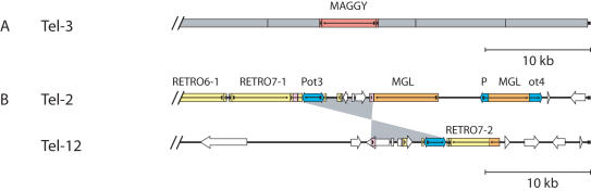
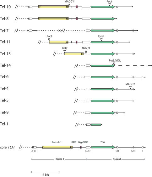
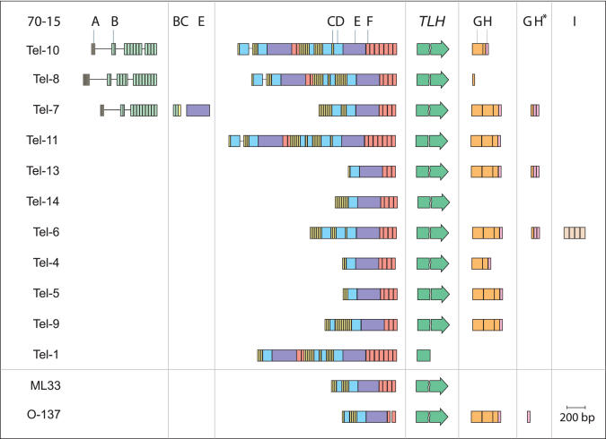
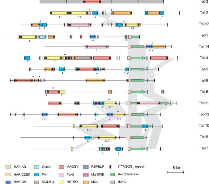
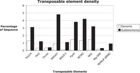
Eukaryotic pathogens of humans often evade the immune system by switching the expression of surface proteins encoded by subtelomeric gene families. To determine if plant pathogenic fungi use a similar mechanism to avoid host defenses, we sequenced the 14 chromosome ends of the rice blast pathogen, Magnaporthe oryzae. One telomere is directly joined to ribosomal RNA-encoding genes, at the end of the approximately 2 Mb rDNA array. Two are attached to chromosome-unique sequences, and the remainder adjoin a distinct subtelomere region, consisting of a telomere-linked RecQ-helicase (TLH) gene flanked by several blocks of tandem repeats. Unlike other microbes, M.oryzae exhibits very little gene amplification in the subtelomere regions-out of 261 predicted genes found within 100 kb of the telomeres, only four were present at more than one chromosome end. Therefore, it seems unlikely that M.oryzae uses switching mechanisms to evade host defenses. Instead, the M.oryzae telomeres have undergone frequent terminal truncation, and there is evidence of extensive ectopic recombination among transposons in these regions. We propose that the M.oryzae chromosome termini play more subtle roles in host adaptation by promoting the loss of terminally-positioned genes that tend to trigger host defenses.
Figures
Similar articles
-
Telomeres in the rice blast fungus Magnaporthe oryzae: the world of the end as we know it.FEMS Microbiol Lett. 2007 Aug;273(2):125-32. doi: 10.1111/j.1574-6968.2007.00812.x. Epub 2007 Jul 4. FEMS Microbiol Lett. 2007. PMID: 17610516 Review.
-
The telomere-linked helicase (TLH) gene family in Magnaporthe oryzae: revised gene structure reveals a novel TLH-specific protein motif.Curr Genet. 2009 Jun;55(3):253-62. doi: 10.1007/s00294-009-0240-3. Epub 2009 Apr 10. Curr Genet. 2009. PMID: 19360408
-
Host specialization of the blast fungus Magnaporthe oryzae is associated with dynamic gain and loss of genes linked to transposable elements.BMC Genomics. 2016 May 18;17:370. doi: 10.1186/s12864-016-2690-6. BMC Genomics. 2016. PMID: 27194050 Free PMC article.
-
Deciphering Genome Content and Evolutionary Relationships of Isolates from the Fungus Magnaporthe oryzae Attacking Different Host Plants.Genome Biol Evol. 2015 Oct 9;7(10):2896-912. doi: 10.1093/gbe/evv187. Genome Biol Evol. 2015. PMID: 26454013 Free PMC article.
-
Investigation of the biological roles of autophagy in appressorium morphogenesis in Magnaporthe oryzae.J Zhejiang Univ Sci B. 2008 Oct;9(10):793-6. doi: 10.1631/jzus.B0860013. J Zhejiang Univ Sci B. 2008. PMID: 18837106 Free PMC article. Review.
Cited by
-
Novel Variation and Evolution of AvrPiz-t of Magnaporthe oryzae in Field Isolates.Front Genet. 2020 Aug 28;11:746. doi: 10.3389/fgene.2020.00746. eCollection 2020. Front Genet. 2020. PMID: 33005166 Free PMC article.
-
An annotated near-complete sequence assembly of the Magnaporthe oryzae 70-15 reference genome.Sci Data. 2025 May 7;12(1):758. doi: 10.1038/s41597-025-05116-3. Sci Data. 2025. PMID: 40335505 Free PMC article.
-
A complete annotation of the chromosomes of the cellulase producer Trichoderma reesei provides insights in gene clusters, their expression and reveals genes required for fitness.Biotechnol Biofuels. 2016 Mar 29;9:75. doi: 10.1186/s13068-016-0488-z. eCollection 2016. Biotechnol Biofuels. 2016. PMID: 27030800 Free PMC article.
-
Directional Selection from Host Plants Is a Major Force Driving Host Specificity in Magnaporthe Species.Sci Rep. 2016 May 6;6:25591. doi: 10.1038/srep25591. Sci Rep. 2016. PMID: 27151494 Free PMC article.
-
Correlation of gene expression and protein production rate - a system wide study.BMC Genomics. 2011 Dec 20;12:616. doi: 10.1186/1471-2164-12-616. BMC Genomics. 2011. PMID: 22185473 Free PMC article.
References
-
- Zakian V.A. Structure, function, and replication of Saccharomyces cerevisiae telomeres. Annu. Rev. Genet. 1996;30:141–172. - PubMed
-
- Walmsley R.W., Chan C.S., Tye B.K., Petes T.D. Unusual DNA sequences associated with the ends of yeast chromosomes. Nature. 1984;310:157–160. - PubMed
-
- Richards E.J., Ausubel F.M. Isolation of a higher eukaryotic telomere from Arabidopsis thaliana. Cell. 1988;53:127–136. - PubMed
-
- Nakamura T.M., Morin G.B., Chapman K.B., Weinrich S.L., Andrews W.H., Lingner J., Harley C.B., Cech T.R. Telomerase catalytic subunit homologs from fission yeast and human. Science. 1997;277:955–959. - PubMed
Publication types
MeSH terms
Substances
Grants and funding
LinkOut - more resources
Full Text Sources
Molecular Biology Databases
Research Materials
Miscellaneous
