

doi: 10.1098/rsif.2006.0151.
Nonlinear mechanics of soft fibrous networks
Affiliations
- PMID: 17015287
- PMCID: PMC2358956
- DOI: 10.1098/rsif.2006.0151
Item in Clipboard
Nonlinear mechanics of soft fibrous networks
J R Soc Interface.
.
Abstract
Mechanical networks of fibres arise on a range of scales in nature and technology, from the cytoskeleton of a cell to blood clots, from textiles and felts to skin and collageneous tissues. Their collective response is dependent on the individual response of the constituent filaments as well as density, topology and order in the network. Here, we use the example of a low-density synthetic felt of athermal filaments to study the generic features of the mechanical response of such networks including strain stiffening and large effective Poisson ratios. A simple microscopic model allows us to explain these features of our observations, and provides us with a baseline framework to understand active biomechanical networks.
Figures
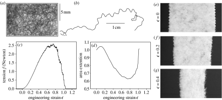
Structure and response of a soft mechanical network. (a) Typical piece of felt. (b) A single polyester fibre (length 7 cm, diameter 30 μm). (c) Response to a uniform strain rate () showing tension versus strain curve. (d) Areal response A(ϵ)/A(0) versus strain ϵ. The increase in the area observed as the felt breaks is due to the felt relaxing back to its initial area as the global tensile stress goes back to zero. (e–g) Width of the felt strip for various imposed strains.
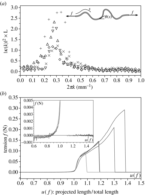
Single fiber characterization. (a) Spatial power spectrum of the fibre curvature showing the squared Fourier amplitudes as a function of the wave number k, presented for five different fibres. L represents the total length for each individual fibre. Inset: schematic of an individual fibre showing the notation used. (b) Force–extension relationship for four single fibres. The inset details the low-force regime. The knee characterizes the onset of plasticity.
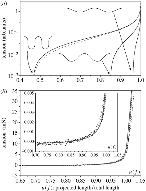
(a) Force–displacement curves for various natural fibre geometries: solid lines correspond to numerical integration of (3.2)–(3.3) and the dashed line to the analytical solution of the linear model (3.3)–(3.4). From right to left, κ0=2.5 cos(2πs), κ0=5 cos(2πs) and κ0=10 cos(2πs). (b) Extension response of a curved fibre (solid line) obtained numerically by solving (3.2)–(3.3) given the measured average power spectrum. The only parameter required to fit the experimental data shown in dashed lines is the bending stiffness (B≈2×10⁻¹⁰ Jm). Inset details the low-force regime.
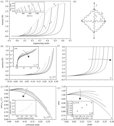
Elastic response of the network. (a) Response of the felt strip to strain cycles of growing amplitude. Inset shows the time evolution of the imposed strain. The strain rate is 4.3×10⁻³ s−1. In a cycle, the dashed curves correspond to the increase in strain and solid curves to the decrease in strain; the latter corresponds to the elastic strain. (b) Tension corrected elastic strain and (c) corrected area as a function of the corrected strain (see text). Inset: measured residual plastic strain ϵi(0) and maximal imposed strain for each cycle i. (d) Minimal network of fibres and its deformation due to an applied force. Results of the network model for the evolution of (e) the tension and (f) the network area as a function of the applied strain, for five different fibres. Inset: the plasticity parameter lt,0 in the network model and its effect on the load-free equilibrated geometry. Forces have been multiplied by 350 in order to match the experimental values; this corresponds roughly to the number of stretched fibres in a section of the strip of felt.

Multiscale approach for fibre response: the dashed line corresponds to the numerical solution of (3.2)–(3.3) and the dotted line approximation (3.3)–(3.4). The solid line is the corrected solution using (A5), (A6) and (A8) for two different shapes (a) κ0(s)=40 cos(16πs)+5 cos(2πs) and (b) κ0(s)=320 cos(128πs)+80 cos(32πs)+20 cos(8πs)+5 cos(2πs). The Insets show the natural shapes of these filaments and a blow-up of the low force-extension regime.
References
-
- Alberts B, Johnson A, Lewis J, Raff M, Roberts K, Walter P. Molecular Biology of the Cell. 2nd edn. Garland Science; New York, NY: 2002.
-
- Blatz P.J, Chu B.M, Wayland H. On the mechanical behavior of elastic animal tissue. Trans. Soc. Rheol. 1969;13:83–102. doi: 10.1122/1.549157. - DOI
-
- Chawla K.K. Cambridge University Press; Cambridge, UK: 1998. Fibrous materials.
MeSH terms
Substances
LinkOut - more resources
Full Text Sources