. 2006 Dec 26;103(52):19771-6.
doi: 10.1073/pnas.0609267103. Epub 2006 Dec 18.

Anisotropy of cell adhesive microenvironment governs cell internal organization and orientation of polarity

Affiliations

Anisotropy of cell adhesive microenvironment governs cell internal organization and orientation of polarity

Manuel Théry et al. Proc Natl Acad Sci U S A. .

Abstract

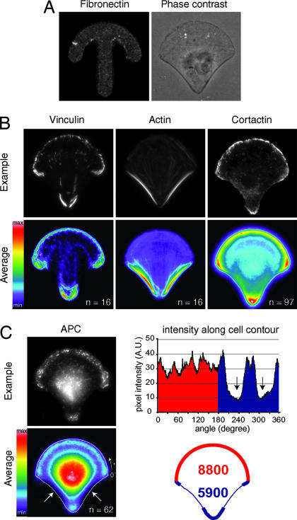
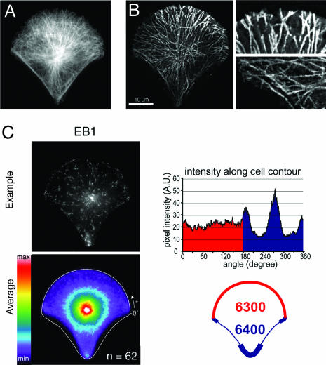
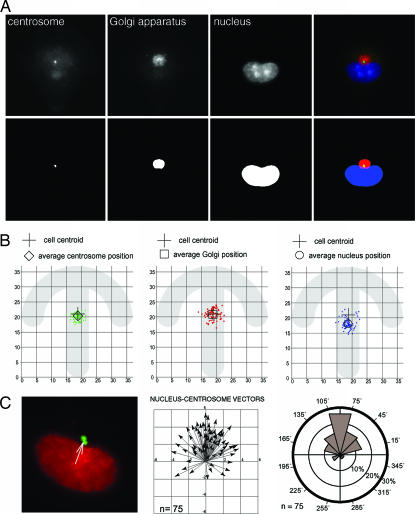
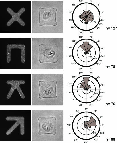
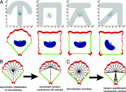
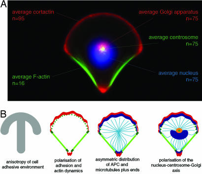
Control of the establishment of cell polarity is an essential function in tissue morphogenesis and renewal that depends on spatial cues provided by the extracellular environment. The molecular role of cell-cell or cell-extracellular matrix (ECM) contacts on the establishment of cell polarity has been well characterized. It has been hypothesized that the geometry of the cell adhesive microenvironment was directing cell surface polarization and internal organization. To define how the extracellular environment affects cell polarity, we analyzed the organization of individual cells plated on defined micropatterned substrates imposing cells to spread on various combinations of adhesive and nonadhesive areas. The reproducible normalization effect on overall cell compartmentalization enabled quantification of the spatial organization of the actin network and associated proteins, the spatial distribution of microtubules, and the positioning of nucleus, centrosome, and Golgi apparatus. By using specific micropatterns and statistical analysis of cell compartment positions, we demonstrated that ECM geometry determines the orientation of cell polarity axes. The nucleus-centrosome orientations were reproducibly directed toward cell adhesive edges. The anisotropy of the cell cortex in response to the adhesive conditions did not affect the centrosome positioning at the cell centroid. Based on the quantification of microtubule plus end distribution we propose a working model that accounts for that observation. We conclude that, in addition to molecular composition and mechanical properties, ECM geometry plays a key role in developmental processes.


Conflict of interest statement

The authors declare no conflict of interest.

Figures

Fig. 1.
Fig. 1.
Cortical polarity. (A) RPE1 cell plated on a fibronectin crossbow micropattern (Left) and visualized in phase contrast (Right). (B) Labelings of vinculin, F-actin, and cortactin (Upper) were averaged over 16–97 cells (Lower). Actin polymerizes in membrane ruffles upon the curved adhesive edge where small dot-like focal adhesions accumulate. Actin assembles in contractile stress fibers anchored to fibronectin via large focal adhesions upon nonadhesive edges. (C) Spatial distribution of APC. Immuno-labelings of APC (Upper Left) were averaged over 62 cells (Lower Left). On the average picture, a 2-μm-wide line scan of pixel intensities along cell contour (white line) shows a reduction of APC density upon nonadhesive edges (arrows). This local reduction induces an imbalance in the spatial distribution of APC. (Right) Integration of pixel intensities along the contour shows a higher content of APC along the adhesive half of the cell (8,800 a.u., red zone) than along the nonadhesive one (5,900 a.u., blue zone).
Fig. 2.
Fig. 2.
Polarization of the MT network. (A) MTs labeled with anti-α-tubulin in a fixed cell platted on a crossbow. (B) EB1 trajectories. (Left) Projection of 100 pictures acquired in time-lapse microscopy at two pictures per s of EB1-GFP in a cell plated on a crossbow (see SI Movie 1). (Right) Magnifications of MT plus ends trajectories show that MTs stop growing when contacting adhesive edges (Upper) and keep growing along nonadhesive edges (Lower). (C) Quantification of the spatial distribution of EB1. (Left) Immuno-labelings of EB1 (Upper) were averaged over 62 cells (Lower). (Right) Line scan of average pixel intensities along the cell contour (Upper) shows reduction of EB1 density along nonadhesive edges and accumulations of EB1 in the area flanking nonadhesive edges. Integration of pixel intensities along the cell contour shows identical amounts of EB1 along both the adhesive half border (6,300 a.u., red zone) and the nonadhesive half border (6,400 a.u., blue zone) (Lower).
Fig. 3.
Fig. 3.
Internal polarity. (A) Labeling of centrosome (green), Golgi apparatus (red), and nucleus (blue) in cells plated on crossbow. The positions of the centroids of these organelles were measured with respect to the underlying micropattern after image segmentation (see Materials and Methods). (Upper) Automated image acquisition. (Lower) Image segmentation. (B) The spatial distributions of centrosome and Golgi positions were clustered around the cell centroid. In contrast, nuclei were off-centered toward nonadhesive edges. (C) (Left) Nucleus centroid and centrosome centroid define the nucleus–centrosome vector. (Center) This vector was used as an indicator of internal cell polarity and measured on 75 cells platted on the crossbow micropattern. X and Y axes represent distances in microns. (Right) The circular histogram represents the proportions of nucleus–centrosome vectors pointing in each angular sector and highlights a clear bias of these orientations relative to the adhesive pattern geometry.
Fig. 4.
Fig. 4.
Orientation of cell polarity depends on the adhesive pattern geometry. (Left) RPE1 cells were plated on fibronectin micropatterns having similar square convex envelops. (Center) Spread cells can be visualized in phase-contrast microscopy. (Right) The corresponding angular distributions of nucleus–centrosome vectors were measured as in Fig. 3. On X, cells displayed a random distribution of cell polarity axis. On the others, cell polarity axis was preferentially orientated from nonadhesive edges toward adhesive edges. Micropatterns are 33.5 μm wide.
Fig. 5.
Fig. 5.
Centrosome positions at the cell center in anisotropic cortical conditions. (A) (Upper) Centrosome positions (green dots) and nuclei positions (blue dots) as measured in Fig. 3A on crossbow (n = 75), C (n = 78), K (n = 76), and arrow (n = 88) are shown. (Lower) As illustrated in the cartoons, centrosomes were close to the geometrical center of the cell contour (cell centroid), whereas nuclei were off-centered toward nonadhesive and contractile edges (green edges). (B) Selective stabilization model. Actin dynamics at the cell cortex (red regions of cell periphery) have been shown to induce a selective stabilization of MTs. MTs contacting adhesive areas where ruffles take place are supposed to be stabilized (arrows) and therefore more amenable to be put under tension than MTs contacting nonruffling area (dashed lines). This selective stabilization, without MT rerouting, would induce an imbalance in the tension exerted on MTs by minus end-directed motors such as dynein. As a consequence centrosome would be off-centered. (C) MT rerouting compensates cortical anisotropy. MTs contacting a nonadhesive edge keep on growing along this edge without being capped. They are rerouted toward an adhesive site where they can be capped. Thereby the local absence of MT capping on nonadhesive part of the cell cortex is compensated by an increase of MT capping in the next adhesive area. This redistribution of MTs would contribute to pull back the centrosome toward the cell center.
Fig. 6.
Fig. 6.
The polarized cell, a standard reference for normalized cell organization. (A) Cell surface polarity propagates to cell internal polarity. This map of internal cell organization on the crossbow micropattern is the combination of several average distributions of cell organelles. Nuclei, centrosomes, or Golgi stainings were averaged over 75 cells and combined to the average distribution of cortactin and F-actin (see Fig. 1). This combination highlights the coherence between cell internal polarity (orientation of the nuclei–centrosome–Golgi axis) and cell surface polarity (mutual exclusion of actin cytoskeleton protrusions and contractions). (B) From external anisotropic boundary conditions up to internal cell polarity. In response to the anisotropic distribution of fibronectin offered by the micropattern (gray) the distribution of adhesions (green) becomes uneven and concentrated at the extremities of nonadhesive edges. The actin network (red) becomes polarized in a polymerizing meshwork on adhesive edges and stress fibers on nonadhesive edges. Actin-MT connectors such as APC (blue) are segregated in membrane ruffling zones and thereby are anisotropically distributed at the cell periphery. MTs stop growing when reaching these regions, whereas they keep growing along nonadhesive edges where stress fibers are developed. The nucleus–centrosome–Golgi apparatus axis is oriented from the nonadhesive side toward the adhesive side. The Golgi apparatus is compacted around the centrosome, which sits at the cell centroid.

References

    1. Nelson WJ. Nature. 2003;422:766–774. - PMC - PubMed
    1. Eaton S, Simons K. Cell. 1995;82:5–8. - PubMed
    1. Drubin DG, Nelson WJ. Cell. 1996;84:335–344. - PubMed
    1. Ridley AJ, Schwartz MA, Burridge K, Firtel RA, Ginsberg MH, Borisy G, Parsons JT, Horwitz AR. Science. 2003;302:1704–1709. - PubMed
    1. Gumbiner BM. Cell. 1996;84:345–357. - PubMed

Publication types

LinkOut - more resources