

Three-dimensional cone-beam computed tomography for assessment of mandibular changes after orthognathic surgery
- PMID: 17208105
- PMCID: PMC3552292
- DOI: 10.1016/j.ajodo.2005.03.029
Three-dimensional cone-beam computed tomography for assessment of mandibular changes after orthognathic surgery
Abstract
Introduction: The purpose of this study was to assess alterations in the 3-dimensional (3D) position of the mandibular rami and condyles in patients receiving either maxillary advancement and mandibular setback or maxillary surgery only.
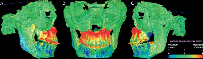
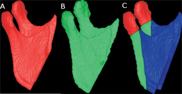
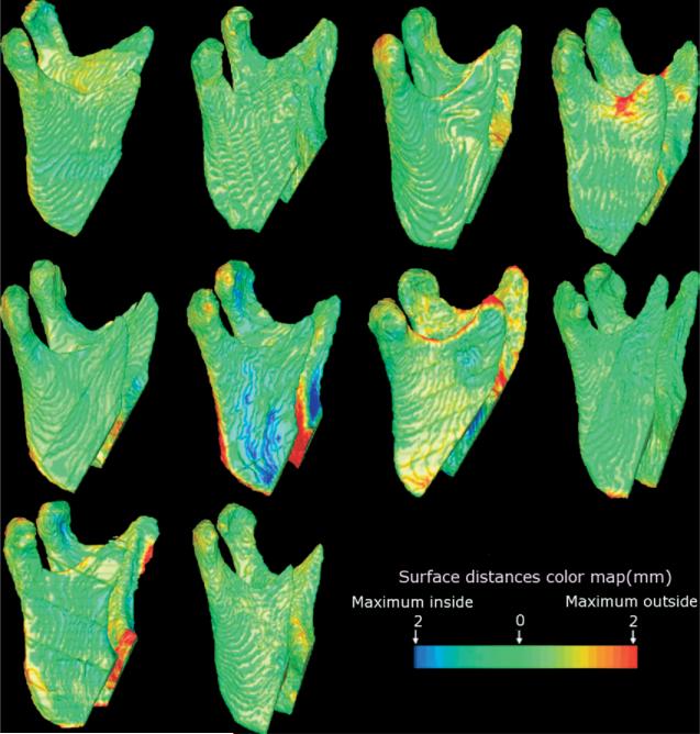
Methods: High-resolution cone-beam computed tomography scans were taken of 21 patients before and after orthognathic surgery. Ten patients with various malocclusions underwent maxillary surgery only, and 11 Class III patients received maxillary advancement and mandibular setback. Presurgery and postsurgery 3D models were registered on the surface of the cranial base. A new tool was used for graphical overlay and 3D display with color maps to visually assess the locations and to quantify positional changes in the posterior border of the mandibular rami and condyles between superimposed models.
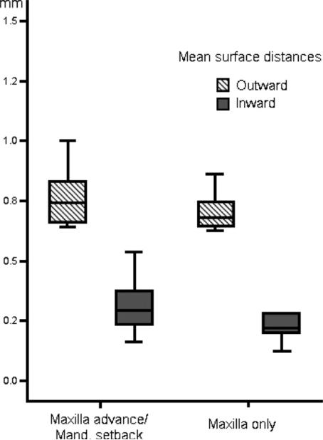
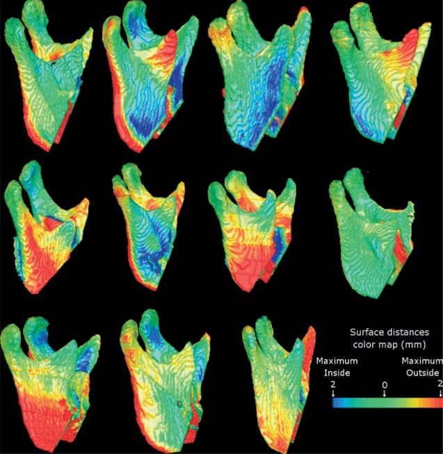
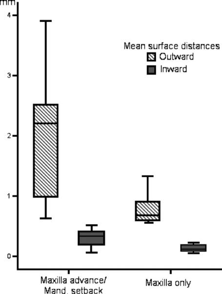
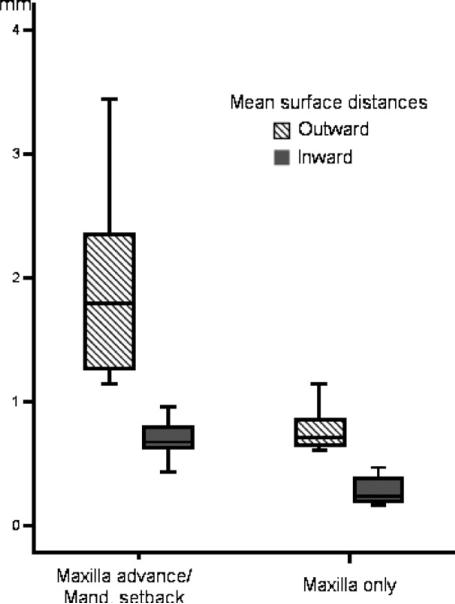
Results: The average displacements in condylar position were small--0.77 mm (SD, 0.12 mm) and 0.70 mm (SD, 0.08 mm)--for 2-jaw and 1-jaw surgeries, respectively (not significant, P >.05). All 2-jaw surgery patients had backward rotational displacements of the mandibular rami (mean, 1.98 mm; SD, 1.03 mm), with a maximum surface distance change of > or =2 mm in 8 of 11 subjects. For the 1-jaw surgery, all subjects had small backward rotational displacements of the mandibular rami (mean, 0.78 mm; SD, 0.25 mm), with only 1 subject having a maximum surface distance change > or =2 mm. The difference in mean backward rotational displacement was statistically significant (P <.01).
Conclusions: The visualization of 3D model superimposition clearly identified the location, magnitude, and direction of mandibular displacement. The 3D imaging allowed quantification of vertical, transverse, and anteroposterior ramus displacement that accompanied mandibular, but not maxillary only, surgery.
Figures
References
-
- Bettega G, Cinquin P, Lebeua J, Raphael B. Computer-assisted orthognathic surgery: clinical evaluation of a mandibular condyle repositioning system. J Oral Maxillofac Surg. 2002;60:27–34. - PubMed
-
- Lee W, Park JU. Three-dimensional evaluation of positional change of the condyle after mandibular setback by means of bilateral sagittal split ramus osteotomy. Oral Surg Oral Med Oral Pathol Oral Radiol Endod. 2002;94:305–9. - PubMed
-
- Kawamata A, Fujishita M, Kuniteru N, Kanematu N, Niwa K, Langlais R. Three-dimensional computed tomography evaluation of postsurgical condylar displacement after mandibular osteotomy. Oral Surg Oral Med Oral Pathol Oral Radiol Endod. 1998;85:371–6. - PubMed
-
- Magalhaes AEO, Stella JP, Tahasuri TH. Changes in condylar position following bilateral sagittal split ramus osteotomy with setback. Int J Adult Orthod Orthognath Surg. 1995;10:137–45. - PubMed
-
- Ueki K, Marukawa K, Nakagawa K, Yamamoto E. Condylar and temporomandibular joint disc positions after mandibular osteotomy for prognathism. J Oral Maxillofac Surg. 2002;60:1424–32. - PubMed
