. 2007 Apr 1;92(7):2546-58.
doi: 10.1529/biophysj.106.094672. Epub 2007 Jan 5.

Attachment conditions control actin filament buckling and the production of forces

Affiliations

Attachment conditions control actin filament buckling and the production of forces

Julien Berro et al. Biophys J. .

Abstract

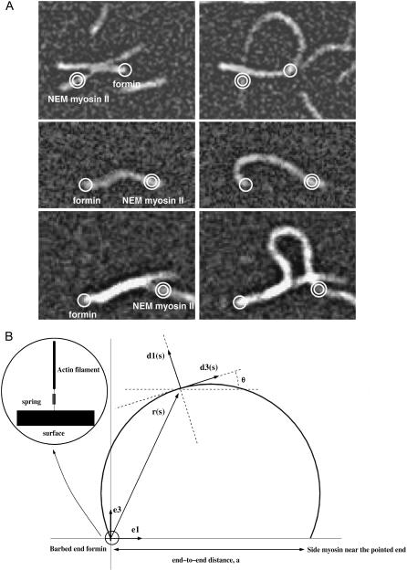
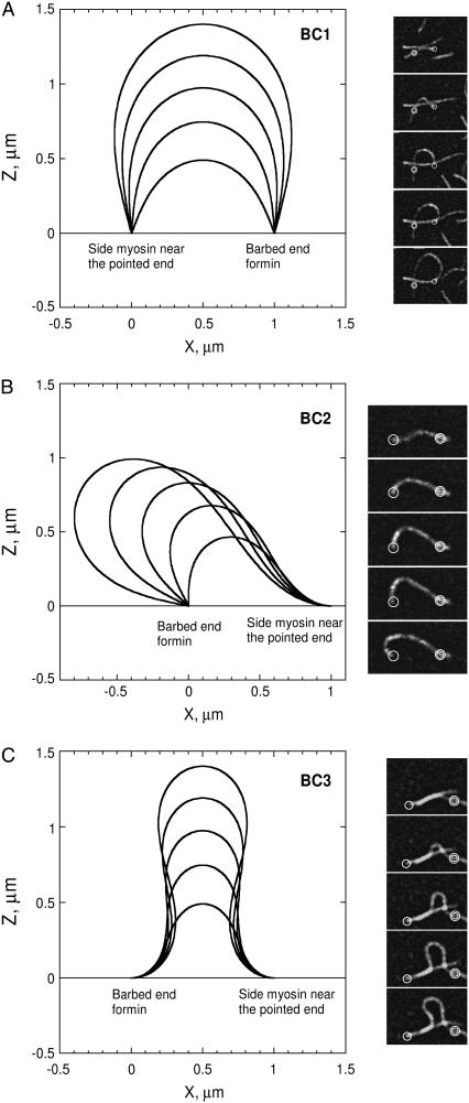
Actin polymerization is the driving force for a large number of cellular processes. Formation of lamellipodia and filopodia at the leading edge of motile cells requires actin polymerization induced mechanical deformation of the plasma membrane. To generate different types of membrane protrusions, the mechanical properties of actin filaments can be constrained by interacting proteins. A striking example of such constraint is the buckling of actin filaments generated in vitro by the cooperative effect of a processive actin nucleating factor (formin) and a molecular motor (myosin II). We developed a physical model based on equations for an elastic rod that accounts for actin filament buckling. Both ends of the rod were maintained in a fixed position in space and we considered three sets of boundary conditions. The model qualitatively and quantitatively reproduces the shape distribution of actin filaments. We found that actin polymerization counterpoises a force in the range 0.4-1.6 pN for moderate end-to-end distance (approximately 1 microm) and could be as large as 10 pN for shorter distances. If the actin rod attachment includes a spring, we discovered that the stiffness must be in the range 0.1-1.2 pN/nm to account for the observed buckling.


Figures

FIGURE 1
FIGURE 1
Buckling of filaments and model. (A) The initial (left column) and buckled configurations (right column) for actin filaments are observed by total internal reflection fluorescence microscopy. Filaments are attached to the microscope slide either by formin (single circle) or NEM myosin II (double circle). (B) Schematic representation of the filament centerline by a curve. A point on the filament, at position r(s), where s is the arclength along the filament centerline, is characterized by the material frame (d1, d3), with d3 tangent to the filament centerline at r(s). The fixed orthogonal set of unit vectors (e1, e3) defines the global orientation of the rod, with the end-to-end vector along the axis e1. During filament buckling, the set of three vectors (r, d1, d3) remains in the plane spanned by (e1, e3). We also define, θ(s), the angle between d3 and e1. L is the total contour length of the filament and a its constant end-to-end distance. (Inset) We model the bond between the filament ends and the surface by an equivalent spring associated with the filament/formin junction.
FIGURE 2
FIGURE 2
Side-by-side comparison of experimental and modeled actin filaments buckling configurations. Typical buckled configurations, calculated for boundary conditions of type 1 (BC1, A, left column), boundary conditions of type 2 (BC2, B, left column), and boundary conditions of type 3 (BC3, C, left column), are compared to their experimental counterpart. (AC, right column) Time-lapse evanescent wave fluorescence microscopy of profilin/rhodamine actin polymerization in the presence of formin (single circle) and NEM-myosin II (double circle) attached to the coverglass. Images were taken every 15 s. All model configurations in panels AC correspond to an end-to-end distance of 1 μm and contour lengths ranging from 1.5 to 3.5 μm. Right column in panel a shows experimental buckling with freely rotating ends (BC1 conditions, end-to-end distance of 3 μm). In panel B, only the left end rotates (BC2 conditions, end-to-end distance of 5 μm) whereas panel C illustrates buckling with fixed horizontal tangent at both ends (BC3 conditions, end-to-end distance of 2 μm).
FIGURE 3
FIGURE 3
Force-contour length relation. (A) The force (boundary conditions BC1, BC2, and BC3, end-to-end distance of 1 μm) is maximal at short filament length, when the rod configuration is almost straight and eventually becomes weaker for longer filaments. (B) The normalized elongation rate, corresponding to curves in panel A (reference is elongation of the free barbed end), is shown as a function of the contour length. For BC1 and BC2 conditions, the tangent force exerted on the filament ends shifts from pushing against an obstacle (L < 2 μm, B) to pulling away from the attachment point (L > 2 μm). This transition occurs when the direction at the filament end is orthogonal to the horizontal end-to-end vector. Conversely, in BC3 conditions, the tangent force pushes the filament against the surface along constant directions and, therefore, the normalized elongation rate is always bounded by 1. We used Lp = 15 μm and end-to-end distance of 1 μm.
FIGURE 4
FIGURE 4
Experimental buckling and model validation. From 113 pooled filament contours (Fig. 3, A and B, in D. Kovar and T. Pollard (13) and unpublished data), we determined the force magnitude as solution of the moment balance equation with BC1 conditions and Lp = 15 μm (Appendix C). The end-to-end distance is ∼5 μm for all data; filament length is in the range 5–12 μm at the end of the elongation period.
FIGURE 5
FIGURE 5
Actin concentration and force at onset buckling. The force (A) and the actin concentration (B) are plotted against the end-to-end distance, for different attachment conditions (BC1, solid line; BC2, dashed line; BC3, dotted line). We use Lp = 15 μm. To appreciate the role of actin in the buckling of short filaments, note that the critical actin monomer concentration for the free barbed end is 0.1 μM.
FIGURE 6
FIGURE 6
Critical bond stiffness. We determine the conditions necessary to hold the filament ends at a distance Δ from the surface for different end-to-end (a) and contour length (L); a is the control parameter and L is given by L/a = 1.1; Lp = 15 μm; Δ is chosen in the range 3–9 nm, i.e., the typical size of one actin monomer (∼6 nm). The curvilinear domain with blue (red) boundaries gives the bond stiffness compatible with the constraint 3 nm < Δ < 9 nm for conditions BC1 (BC2). For both kind of boundary conditions, the top (respectively, bottom) border, indicated by red and blue squares, is associated with Δ = 3 nm (Δ = 9 nm, red and blue dots). The vertical borders, indicated by blue and red triangles, are determined by the condition Lc < L (Eqs. D-3 and D-4); below this limit, no buckling occurs, whatever the bond robustness.

References

    1. Pollard, T. D., and G. G. Borisy. 2003. Cellular motility driven by assembly and disassembly of actin filaments. Cell. 112:453–465. - PubMed
    1. Pruyne, D., M. Evangelista, C. Yang, E. Bi, S. Zigmond, A. Bretscher, and C. Boone. 2002. Role of formins in actin assembly: nucleation and barbed-end association. Science. 297:612–615. - PubMed
    1. Sagot, I., S. K. Klee, and D. Pellman. 2002. Yeast formins regulate cell polarity by controlling the assembly of actin cables. Nat. Cell Biol. 4:42–50. - PubMed
    1. Chang, F., D. Drubin, and P. Nurse. 1997. cdc12p, a protein required for cytokinesis in fission yeast, is a component of the cell division ring and interacts with profilin. J. Cell Biol. 137:169–182. - PMC - PubMed
    1. Tominaga, T., E. Sahai, P. Chardin, F. McCormick, S. A. Courtneidge, and A. S. Alberts. 2000. Diaphanous-related formins bridge Rho GTPase and Src tyrosine kinase signaling. Mol. Cell. 5:13–25. - PubMed

Substances

LinkOut - more resources