

Hyperpolarized water as an authentic magnetic resonance imaging contrast agent
- PMID: 17264210
- PMCID: PMC1794264
- DOI: 10.1073/pnas.0610540104
Hyperpolarized water as an authentic magnetic resonance imaging contrast agent
Abstract
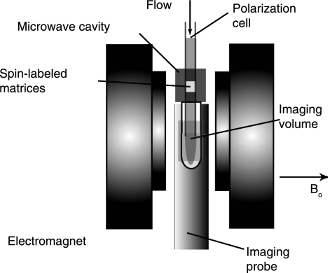
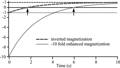
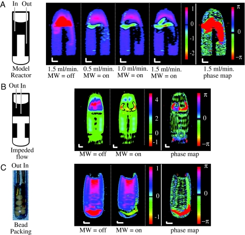
Pure water in a highly (1)H spin-polarized state is proposed as a contrast-agent-free contrast agent to visualize its macroscopic evolution in aqueous media by MRI. Remotely enhanced liquids for image contrast (RELIC) utilizes a (1)H signal of water that is enhanced outside the sample in continuous-flow mode and immediately delivered to the sample to obtain maximum contrast between entering and bulk fluids. Hyperpolarization suggests an ideal contrast mechanism to highlight the ubiquitous and specific function of water in physiology, biology, and materials because the physiological, chemical, and macroscopic function of water is not altered by the degree of magnetization. We present an approach that is capable of instantaneously enhancing the (1)H MRI signal by up to 2 orders of magnitude through the Overhauser effect under ambient conditions at 0.35 tesla by using highly spin-polarized unpaired electrons that are covalently immobilized onto a porous, water-saturated gel matrix. The continuous polarization of radical-free flowing water allowed us to distinctively visualize vortices in model reactors and dispersion patterns through porous media. A (1)H signal enhancement of water by a factor of -10 and -100 provides for an observation time of >4 and 7 s, respectively, upon its injection into fluids with a T(1) relaxation time of >1.5 s. The implications for chemical engineering or biomedical applications of using hyperpolarized solvents or physiological fluids to visualize mass transport and perfusion with high and authentic MRI contrast originating from water itself, and not from foreign contrast agents, are immediate.
Conflict of interest statement
The authors declare no conflict of interest.
Figures
Similar articles
-
Continuous flow Overhauser dynamic nuclear polarization of water in the fringe field of a clinical magnetic resonance imaging system for authentic image contrast.J Magn Reson. 2010 Aug;205(2):247-54. doi: 10.1016/j.jmr.2010.05.008. Epub 2010 May 19. J Magn Reson. 2010. PMID: 20541445 Free PMC article.
-
Characterization and optimization of the visualization performance of continuous flow overhauser DNP hyperpolarized water MRI: Inversion recovery approach.Magn Reson Med. 2016 Mar;75(3):985-96. doi: 10.1002/mrm.25574. Epub 2015 Apr 17. Magn Reson Med. 2016. PMID: 25884985
-
Overhauser dynamic nuclear polarization amplification of NMR flow imaging.J Magn Reson. 2012 Mar;216:94-100. doi: 10.1016/j.jmr.2012.01.007. Epub 2012 Jan 28. J Magn Reson. 2012. PMID: 22329973
-
Hyperpolarized agents for advanced MRI investigations.Q J Nucl Med Mol Imaging. 2009 Dec;53(6):604-17. Q J Nucl Med Mol Imaging. 2009. PMID: 20016452 Review.
-
Pushing the sensitivity envelope of lanthanide-based magnetic resonance imaging (MRI) contrast agents for molecular imaging applications.Acc Chem Res. 2009 Jul 21;42(7):822-31. doi: 10.1021/ar800192p. Acc Chem Res. 2009. PMID: 19534516 Review.
Cited by
-
A versatile synthetic route to the preparation of 15 N heterocycles.J Labelled Comp Radiopharm. 2019 Nov;62(13):892-902. doi: 10.1002/jlcr.3699. Epub 2019 Jan 7. J Labelled Comp Radiopharm. 2019. PMID: 30537260 Free PMC article.
-
Spin Hyperpolarization in Modern Magnetic Resonance.Chem Rev. 2023 Feb 22;123(4):1417-1551. doi: 10.1021/acs.chemrev.2c00534. Epub 2023 Jan 26. Chem Rev. 2023. PMID: 36701528 Free PMC article. Review.
-
Biomolecular MRI reporters: Evolution of new mechanisms.Prog Nucl Magn Reson Spectrosc. 2017 Nov;102-103:32-42. doi: 10.1016/j.pnmrs.2017.05.002. Epub 2017 Jun 3. Prog Nucl Magn Reson Spectrosc. 2017. PMID: 29157492 Free PMC article. Review.
-
Benzoquinone Enhances Hyperpolarization of Surface Alcohols with Para-Hydrogen.J Am Chem Soc. 2023 May 10;145(18):9970-9975. doi: 10.1021/jacs.3c01593. Epub 2023 Apr 26. J Am Chem Soc. 2023. PMID: 37127286 Free PMC article.
-
Increasing hyperpolarized spin lifetimes through true singlet eigenstates.Science. 2009 Mar 27;323(5922):1711-4. doi: 10.1126/science.1167693. Science. 2009. PMID: 19325112 Free PMC article.
References
-
- Law M, Hamburger M, Johnson G, Inglese M, Londono A, Golfinos J, Zagzag D, Knopp EA. Technol Cancer Res Treatment. 2004;3:557–565. - PubMed
-
- Wintermark M, Sesay M, Barbier E, Borbely K, Dillon WP, Eastwood JD, Glenn TC, Grandin CB, Pedraza S, Soustiel J-F, et al. Stroke. 2005;36:e83–e99. - PubMed
-
- Lurie DJ, Bussell DM, Bell LH, Mallard JR. J Magn Reson. 1988;76:366–370.
-
- Grucker D. Magn Reson Med. 1990;14:140–147. - PubMed
-
- Golman K, Petersson JS, Ardenkjær-Larsen J-H, Leunbach I, Wistrand L-G, Ehnholm G, Liu K. J Magn Reson Imaging. 2000;12:929–938. - PubMed
Publication types
MeSH terms
Substances
LinkOut - more resources
Full Text Sources
Other Literature Sources
Medical
