. 2007 Apr 13;367(5):1447-58.
doi: 10.1016/j.jmb.2007.01.078. Epub 2007 Feb 7.

Structure and interactions of the first three RNA recognition motifs of splicing factor prp24

Affiliations

Structure and interactions of the first three RNA recognition motifs of splicing factor prp24

Euiyoung Bae et al. J Mol Biol. .

Abstract

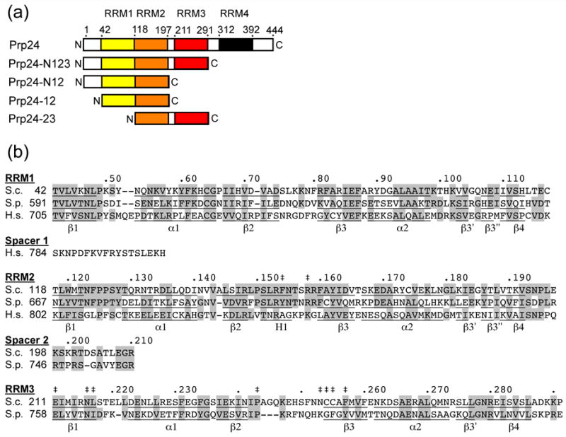
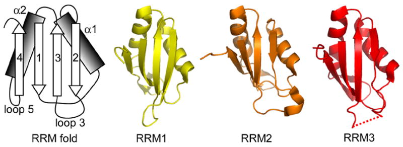
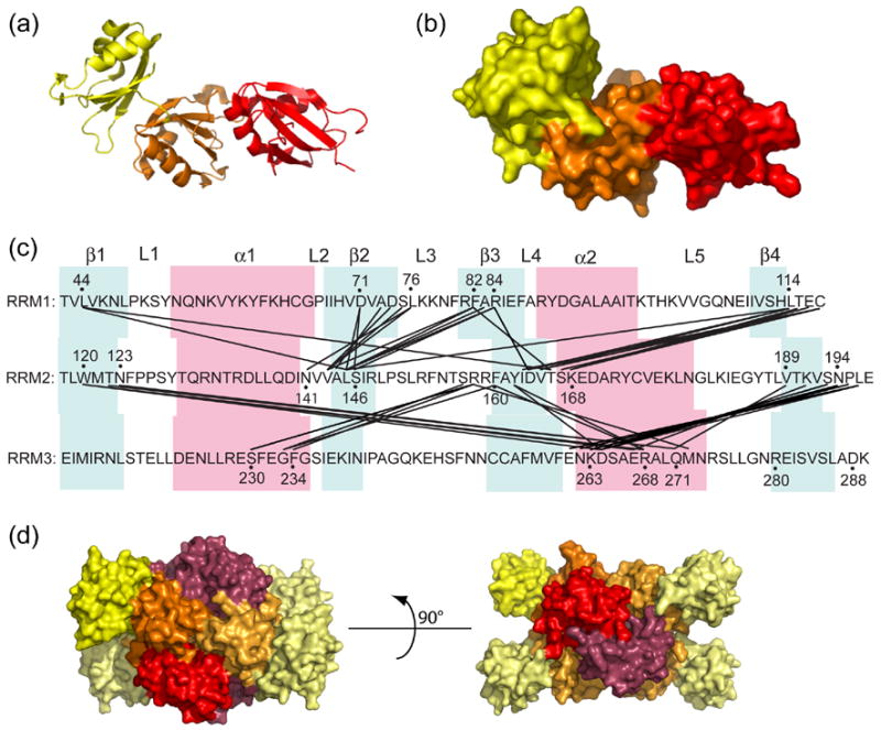
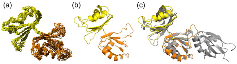
The essential Saccharomyces cerevisiae pre-messenger RNA splicing protein 24 (Prp24) has four RNA recognition motifs (RRMs) and facilitates U6 RNA base-pairing with U4 RNA during spliceosome assembly. Prp24 is a component of the free U6 small nuclear ribonucleoprotein particle (snRNP) but not the U4/U6 bi-snRNP, and so is thought to be displaced from U6 by U4/U6 base-pairing. The interaction partners of each of the four RRMs of Prp24 and how these interactions direct U4/U6 pairing are not known. Here we report the crystal structure of the first three RRMs and the solution structure of the first two RRMs of Prp24. Strikingly, RRM 2 forms extensive inter-domain contacts with RRMs 1 and 3. These contacts occupy much of the canonical RNA-binding faces (beta-sheets) of RRMs 1 and 2, but leave the beta-sheet of RRM 3 exposed. Previously identified substitutions in Prp24 that suppress mutations in U4 and U6 spliceosomal RNAs cluster primarily in the beta-sheet of RRM 3, but also in a conserved loop of RRM 2. RNA binding assays and chemical shift mapping indicate that a large basic patch evident on the surface of RRMs 1 and 2 is part of a high affinity U6 RNA binding site. Our results suggest that Prp24 binds free U6 RNA primarily with RRMs 1 and 2, which may remodel the U6 secondary structure. The beta-sheet of RRM 3 then influences U4/U6 pairing through interaction with an unidentified ligand.


Figures

Figure 1
Figure 1
Primary structure and conservation of Prp24. (a) Domain structure of S. cerevisiae Prp24. The four RRMs are represented in different colors and the approximate boundaries of the four RRMs are indicated by amino acid residue number. Truncation constructs used in this study are shown below the full-length protein; see Materials and Methods for precise endpoints of constructs. (b) Sequence conservation of RRMs 1–3 in S. cerevisiae (S.c), Schizosaccharomyces pombe (S.p.), and human (H.s.) Prp24. S. pombe and human Prp24 have long N-terminal domains (not shown), and human Prp24 has only two RRMs. Identical and highly similar residues are highlighted grey. A dot marks every 10th residue in the S.c. sequence. Secondary structure elements are underlined and labeled (α = alpha helix, β = beta sheet, H = 310 helix). Double-daggers (‡) indicate the positions of mutations that suppress U6-A62G or U4-G14C, which include L217P, N253S, and C255R (U4-G14C) and F154S, R158S, E211D, N216H, P243S, C254W, and F257I (U6-A62G).
Figure 2
Figure 2
RRMs 1, 2 and 3 in Prp24-N123 crystal structure. The RRMs adopt canonical folds. The schematic at left shows the canonical β–α– β– β–α– β RRM fold, with the β-strands and α-helices numbered in order from the N-terminus. The backbone structure of RRMs 1–3 is shown at right. The dotted line indicates a disordered region in loop 3 of RRM 3.
Figure 3
Figure 3
Interactions between RRMs 1, 2 and 3 of Prp24. (a) Ribbon diagram of Prp24-N123, with the RRMs colored as in Figures 1 and 2. (b) Surface structure of Prp24-N123, in the same orientation as panel A. (c) Map of inter-RRM interactions. Residues in two different RRMs that are within 4.0 Å distance from one another are connected by black lines. β-strands are highlighted in blue, and α-helices in pink. Loops between secondary structure elements are labeled L1–L5. (d) Surface structure of a Prp24-N123 tetramer (chains A–D) from the crystal structure. The three RRMs in chain B are colored as in Figure 1 and 2. Chains A, C and D are colored similar to chain B, but are light yellow, light orange and red-purple for RRMs 1–3, respectively.
Figure 4
Figure 4
Solution structure of Prp24-12. (a) Ensemble of ten energy-minimized NMR structures of Prp24-12. The backbone RMSD of secondary structure-containing regions of RRMs 1 (yellow) and 2 (orange) is 0.97 Å ± 0.09. (b) Ribbon diagram of the lowest free energy structure of Prp24-12, with RRMs colored as in Figures 1–3. (c) Comparison of the mean NMR and crystal (depicted in grey) structures. Backbone atoms of secondary structure regions were fit to RRM domains 1 and 2 and give an RMSD of 2.0 Å ± 0.3 (Supplementary Table III).
Figure 5
Figure 5
Dynamics of Prp24 RRMs 1, 2 and 3. Average backbone B-factors, 15N heteronuclear NOE values, and 15N T1/T2 relaxation time ratios are plotted versus the protein sequence (residues 41–291). Open circles are data points from the Prp24-N123 crystal structure, and filled diamonds and open squares are from NMR experiments on Prp24-12 and -23, respectively. B-factor errors incorporate the eight Prp24 chains present in the crystallographic asymmetric unit. Two Prp24-12 and Prp24-23 15N heteronuclear NOE data sets were acquired, analyzed, and incorporated into error calculations. For the T1/T2 ratio data sets, errors represent multiple 15N T1 and T2 relaxation experiments in addition to the uncertainty of the exponential fit. Disorderd regions in the crystal structure are shaded in grey (residues 151–157, 196–207 and 245–251).
Figure 6
Figure 6
Location of U4-G14C and U6-A62G suppressor mutations in RRMs 2 and 3 of Prp24. The backbone of RRM 2 is shown in orange and RRM 3 in red. Residues at which U4-G14C (green) or U6-A62G (blue) suppressor substitutions were selected are shown in space-fill mode. Two views related by a 90° rotation about the vertical axis are shown. See Figure 1(b) for the identity of the residues shown.
Figure 7
Figure 7
Binding of truncated Prp24 proteins to a domain of U6 RNA. (a) Primary and possible secondary structure of a minimal U6 RNA construct (40-nucleotide RNA) used in gel mobility shift assays (S. cerevisiae nucleotides 41–64 and 83–88 are boxed). 15N-labeled (b) Prp24-N123 and (c) Prp24-N12 proteins at concentrations of 0, 25, 50, 100, 200, 400, and 800 nM (lanes 1–7, respectively) were incubated with 32P-labeled 40-nucleotide RNA and resolved on a 6% native polyacrylamide gel. (d) Fraction of RNA bound plotted against the total concentration of Prp24-N123 (open circles), N12 (filled diamonds), and 23 (open squares). Data were fit to a one-site hyperbolic binding function (Y= (Bmax*X)/{Kd +X}), where Y is the fraction bound and X is the concentration of Prp24. The apparent Kd (in nM) is 45 ± 10 for Prp24-N123 and 81 ± 10 for Prp24-N12. An accurate apparent Kd value could not be extrapolated for Prp24-23.
Figure 8
Figure 8
Mapping of U6 RNA binding interactions on the surface of Prp24. (a) Region of the 1H-15N HSQC-TROSY spectra showing amide peaks of 0.2 mM 2H,15N-labeled Prp24-N12 protein in the absence (black) and presence (red) of 50 μM 21-nucleotide RNA (yeast U6 nucleotides 40–60). Assigned resonances that are selectively line broadened upon the addition of RNA are circled in magenta and labeled. (b) Location of the line broadened amino acids (shown in magenta) in the crystal structure. The structure at left is in the same orientation as is shown in Figures 3(a) and 3B, and is rotated 180° around the vertical axis relative to the structure at right. The ribbon is colored as in Figure 1. (c) Electrostatic potential isosurface of the Prp24-N123 crystal structure calculated by the Poisson-Boltzmann equation. The isosurface is contoured at ± 4 kT and is superposed on the molecular surface (white). A prominent electropositive region (blue) exists on one side of the protein, possibly corresponding to an RNA binding site. Electronegative regions (red) are small and distributed more uniformly around the protein. Structures are in the same orientation as in Figure 8(b).

References

    1. Will CL, Lührmann R. Spliceosome structure and function. In: Gesteland RF, Cech TR, Atkins JF, editors. The RNA World. 3. Cold Spring Harbor Laboratory Press; Cold Spring Harbor, NY: 2006. pp. 369–400.
    1. Staley JP, Guthrie C. Mechanical devices of the spliceosome: motors, clocks, springs, and things. Cell. 1998;92:315–26. - PubMed
    1. Brow DA. Allosteric cascade of spliceosome activation. Annu Rev Genet. 2002;36:333–60. - PubMed
    1. Herschlag D. RNA chaperones and the RNA folding problem. J Biol Chem. 1995;270:20871–4. - PubMed
    1. Schroeder R, Barta A, Semrad K. Strategies for RNA folding and assembly. Nat Rev Mol Cell Biol. 2004;5:908–19. - PubMed

Publication types

MeSH terms