. 2007 Jul;35(7):1247-63.
doi: 10.1007/s10439-007-9277-y. Epub 2007 Mar 22.

The role of 3-canal biomechanics in angular motion transduction by the human vestibular labyrinth

Affiliations

The role of 3-canal biomechanics in angular motion transduction by the human vestibular labyrinth

Marytheresa A Ifediba et al. Ann Biomed Eng. 2007 Jul.

Abstract

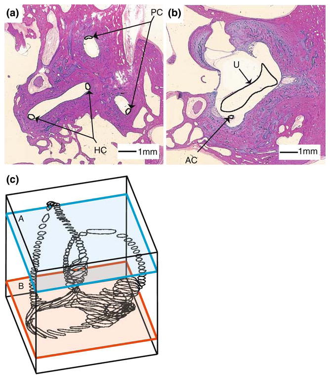
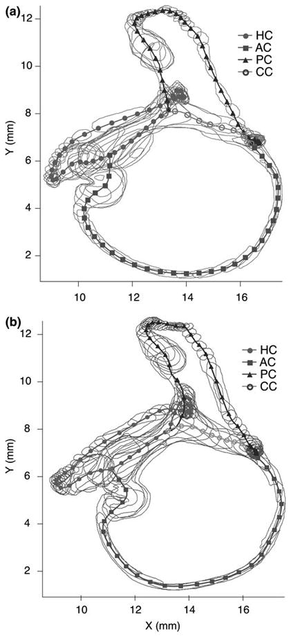
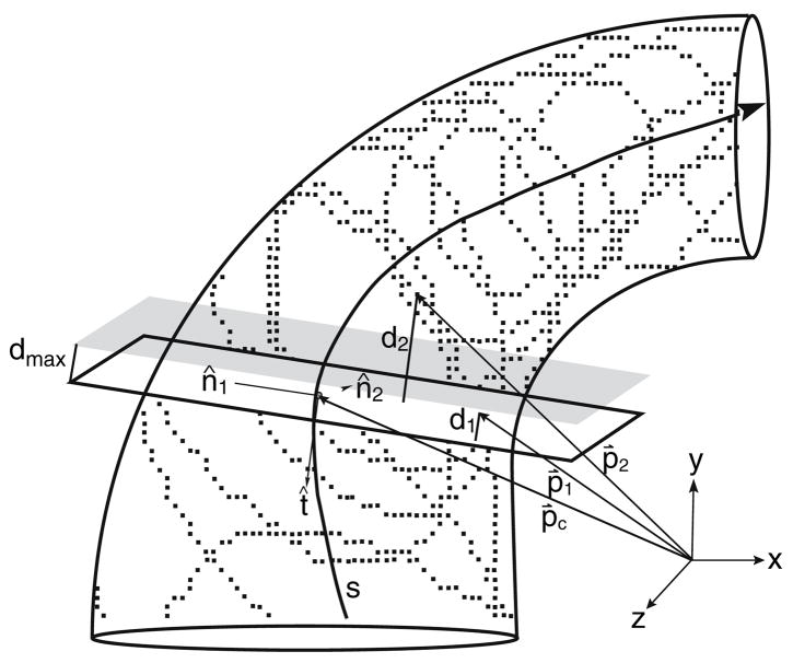
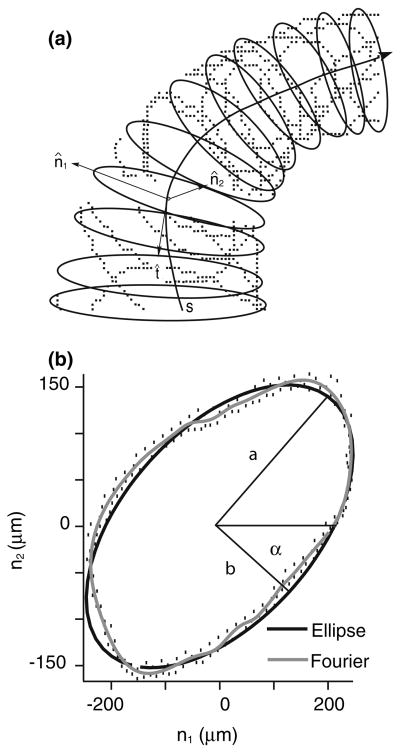
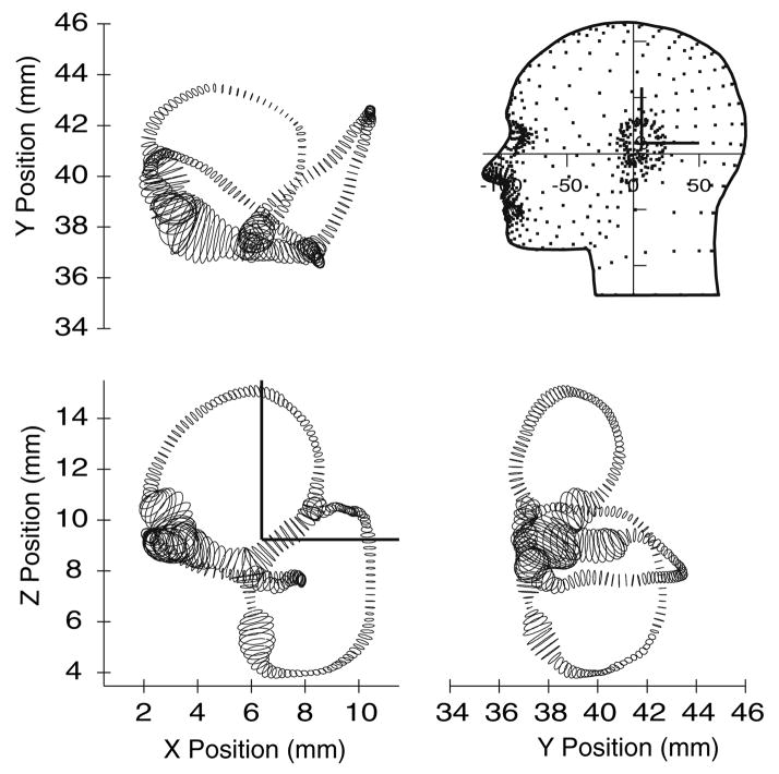
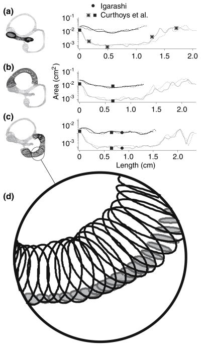
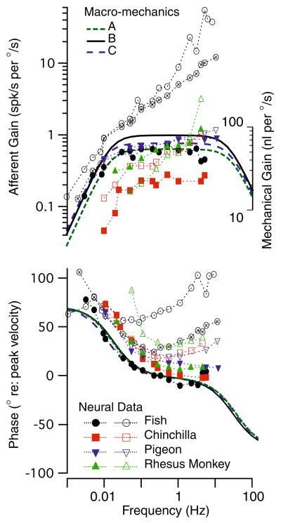
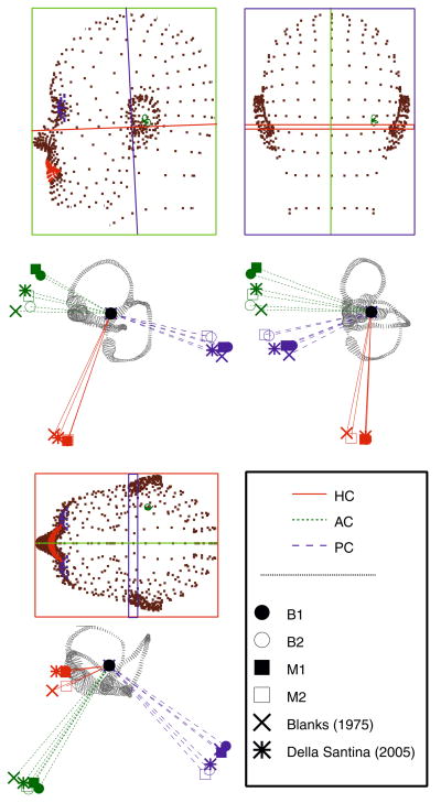
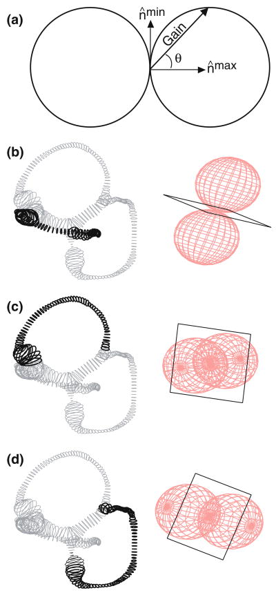
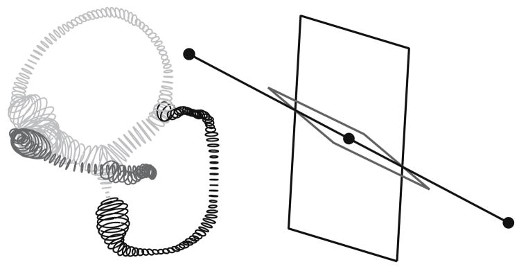
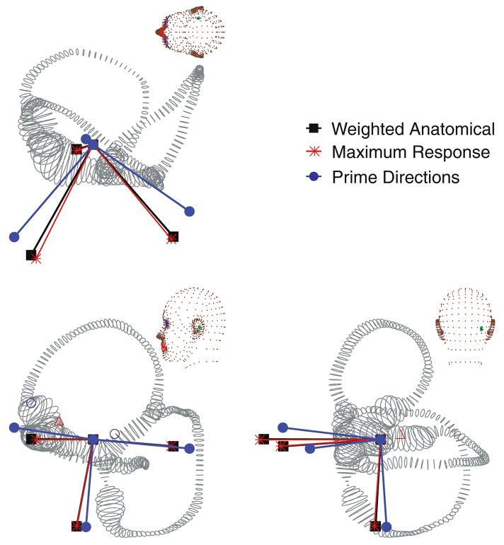
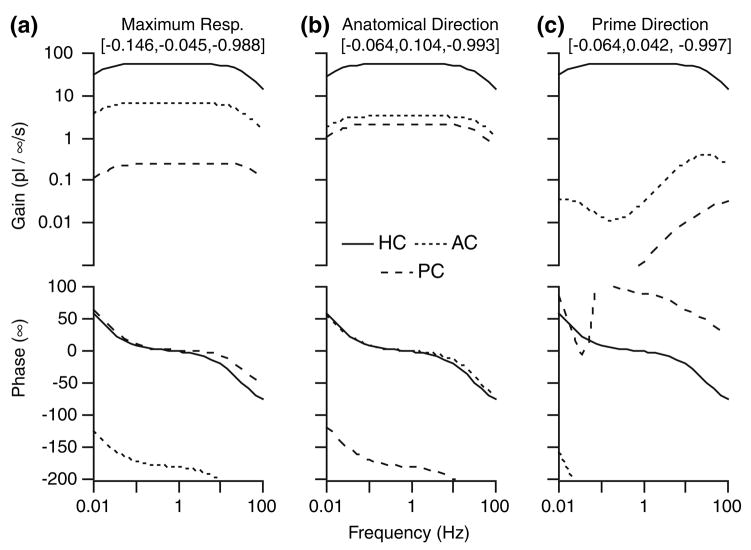
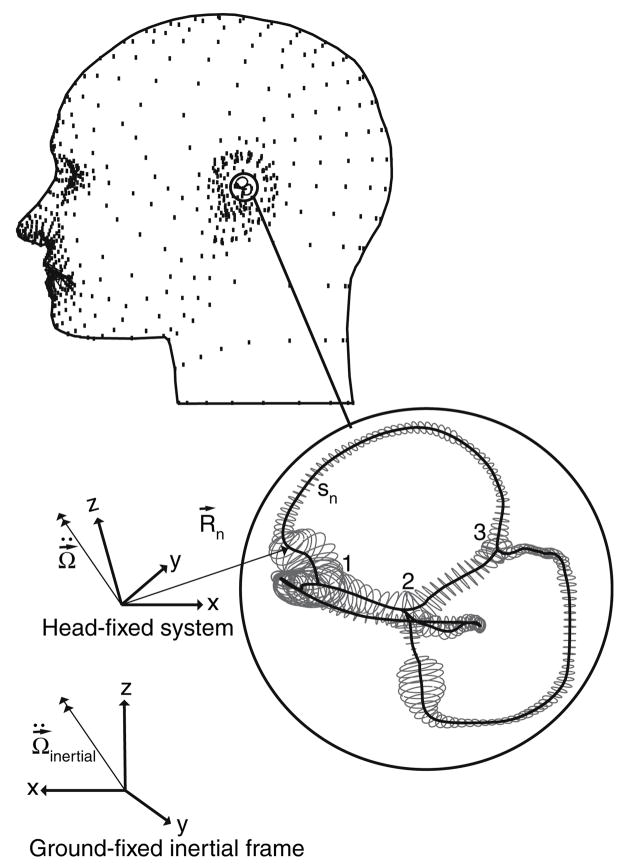
The present work examines the role of the complex geometry of the human vestibular membranous labyrinth in the process of angular motion transduction by the semicircular canals. A morphologically descriptive mathematical model was constructed to address the biomechanical origins of temporal signal processing and directional coding in determining the inputs to the brain. The geometrical model was developed based on shrinkage-corrected temporal bone sections using a segmentation/data-fitting procedure. Endolymph fluid dynamics within the 3-canal labyrinth was modeled using an asymptotic form of the Navier-Stokes equations and solved to estimate endolymph and cupulae volume displacements. The geometrical model was manipulated to study the role of major morphological features on directional and temporal coding. Anatomical results show that the bony osseous canals provide reasonable estimates of the orientation of the delicate membranous canals--the two differed by only 3.48 +/- 1.89 degrees . Biomechanical results show that the maximal response directions are distinct from the anatomical canal planes, but can be closely approximated by fitting a flat plane to the centerline of the canal of interest and weighting each location along the centerline with the inverse of the cross-sectional area squared. Vector cross-products of these maximal response directions, in turn, determine the null planes and prime directions that transmit the direction of angular motion to the brain as three independent directional channels associated with the nerve bundles. Finally, parameter studies indicate that changes in canal cross-sectional area and shape only moderately affect canal temporal and directional coding, while three-canal orientation is critical to directional coding.


Figures

FIGURE 1
FIGURE 1
Segmentation of the human labyrinth. Two representative histological sections (a, b) are shown with the membranous labyrinth outline in black and labeled. Segmented sections were stacked to form the three-dimensional outline of the endolymphatic space (c).
FIGURE 2
FIGURE 2
Labyrinth centerlines. The segmented endolymphatic space is shown for the two labyrinths (a, b) with the centerlines for the canals (HC, AC, PC) and the CC indicated. The utricular vestibule centerline was incorporated into that of the HC. Center points (symbols) were calculated at even intervals along the curved centerline of each canal and used to define local coordinate systems aligned tangent to the canal centerline.
FIGURE 3
FIGURE 3
Slice selection. For each point along the centerline of a canal, a local coordinate system composed of tangent, normal and binormal vectors (, 1 and 2, respectively) was calculated directly from the centerline, s. A ~500 μm-thick slice was cut transverse to the canal as follows. If c is a vector extending from the origin of the global coordinate system to the center point, and n (n = 1,2,…) are vectors from the global system origin to the data points comprising the endolymphatic space, then dn, the distance between a data point and a plane centered at the center point and perpendicular to the tangent vector (white plane) is given by the equation: dn=t^(pˇnpˇc)t^||(pˇnpˇc). To designate slice thickness, only points of dn < dmax are selected, corresponding to points falling between the white and shaded planes. In the specific case of 500-μm slices, dmax is set to 250 μm (e.g., the point of distance d1 would be selected as part of the slice while the point of distance d2 would not).
FIGURE 4
FIGURE 4
Data fitting. A 10-term Fourier series, an ellipse (2-term Fourier series) and a circle (1-term Fourier series) were fitted to the selected slice of data points (Fig. 3) at each center point using least squares. The resulting fitted contours lie in the normal (1) − (s)plane and define the cross-sectional area perpendicular to the centerline tangent vector (a). The 10-term Fourier series curve (b, gray contour) closely reproduced details of the canal cross-sectional shape, but overall the shape and cross-sectional area were well represented by an ellipse (b, black contour; also see Results).
FIGURE 5
FIGURE 5
Orthographic views of the human membranous labyrinth. The reconstruction is presented with +x as posterior, +y as right lateral, and +z as superior (note direction of y). Labyrinths were reconstructed relative to histological block coordinates and placed within the head by minimizing the difference between the bony canals in the histological data and the average bony canals localized previously using CT data (Della Santina et al. 2005).
FIGURE 6
FIGURE 6
Cross-sectional area functions. Bony canal (black) and membranous duct (gray) cross-sectional area functions are shown each canal duct are shown for the HC (a), AC (b) and PC (c). Solid curves are for labyrinth 1 and dashed curves are for labyrinth 2. The membranous ducts are defined to extend from the cupula, along the canal, down the CC and/or utricle, and back to the cupula. Comparable membranous labyrinth measures by Igarashi, Curthoys et al. and Curthoys et al. are designated by a solid circle, a solid square, and an asterisk, respectively. Also shown is an enlarged view of the labyrinth (d), which emphasizes the order of magnitude difference between the areas of the bony (white filled ellipses) and membranous canals (gray filled ellipses).
FIGURE 7
FIGURE 7
Frequency response. Model predictions for the volume displacement of the cupula (A–C) are shown along with semicircular canal neural afferent gain and phase (fish: Boyle and Highstein; chinchilla: Baird et al.; pigeon: Dickman et al.; rhesus monkey: Haque et al.21). Note that the biomechanical predictions correspond reasonably well with some afferents (e.g., solid symbols, low-gain and regular units), while other afferents have phase and gain enhancements due to hair-cell afferent signal processing. The effect of shrinkage (compare A, B and C) on mechanical responses, although significant, is quite small relative to non-mechanical factors influencing gain, phase and the temporal signal transmitted to the brain (Rabbitt et al.32).
FIGURE 8
FIGURE 8
Anatomical canal planes. Orthographic views of canal plane normal vectors for the bony canals of the two labyrinths (B1, B2) and the membranous ducts of each labyrinth (M1, M2). It is notable that the bony canals and membranous ducts aligned quite well in the present study. Results are displayed along with previous results for the bony canals by Blanks et al. and Della Santina et al., The stereotactic reference frames defined by Reid’s planes are shown with respect to the human head. Below each is a view of labyrinth from the same vantage point.
FIGURE 9
FIGURE 9
Maximal response directions. For any sinusoidal head rotation, the gain of the cupular volume displacement is proportional to the cosine of the angle (θ) between the axis of rotation and the maximal response directions (nmax) as illustrated by the vector from the origin to the surface of a circle (a). The three-dimensional cosine rule takes the form of a spherical bubble, shown here for the HC (b), AC (c), and PC (d). The vector nmin (a) represents an axis of rotation for which minimal response is elicited. A “null plane” is defined by a group of such vectors, and are illustrated as black squares for the HC (b), AC (c), and PC (d).
FIGURE 10
FIGURE 10
Prime directions. Prime directions are defined as the axis of rotation that nulls the responses of two sister canals while maintaining a large response in only one canal. They are defined by the intersection of the null planes of sister canals. The prime direction (dumbbell) of the posterior canal is illustrated here as the intersection of the HC and AC null planes (rectangles).
FIGURE 11
FIGURE 11
Canal coordinate systems. Semicircular canals have three natural coordinate systems: anatomical canal planes, maximal response directions and prime directions. The three directions are illustrated for an example labyrinth. Anatomical canal planes were determined by fitting a plane to the canal center line data and weighting the fit with the inverse of the local duct cross-sectional area squared. Maximal response directions denote the direction of rotation that elicits the maximal cupular volume displacement, and prime directions denote the direction of rotation that nulls the responses of the sister canals. There is a weak frequency dependence on the prime and maximal response directions (shown here at 0.3 Hz).
FIGURE 12
FIGURE 12
Sensitivity for rotations in three key planes. Bode plots quantify cupula responses for sinusoidal rotations in the anatomical canal plane (a), about the maximal response direction (b), and about the prime direction (c) of the HC (see Fig. 11). Although all three rotations result in very similar gain and phase of the HC cupula, only rotation about the prime direction (c) results in large gain responses in the HC and simultaneous “inactivation” of the AC and PC.
FIGURE 13
FIGURE 13
FIGURE A.1. Model labyrinth geometry. The human membranous labyrinth has 3 natural bifurcation points (1–3) where the six labyrinthine segments join. The three-dimensional motion of each segment was specified by time-dependent angular acceleration in the ground-fixed intertial frame and resolved into the moving head-fixed system. This introduces a Galilean transformation and an inertial force that appears in the Navier–Stokes equations. Poiseuille flow and slender body approximations were assumed to further reduce the equations to a set of coupled ordinary equations (Damiano and Rabbitt14). Equations for six segments were coupled together at the bifurcations by conservation of mass and pressure continuity.

Similar articles

Cited by

References

    1. Arnold B, Jager L, Grevers G. Visualization of inner ear structures by three-dimensional high-resolution magnetic resonance imaging. Am J Otol. 1996;17(3):480–485. - PubMed
    1. Baird RA, et al. The vestibular nerve of the chinchilla. II. Relation between afferent response properties and peripheral innervation patterns in the semicircular canals. J Neurophysiol. 1988;60(1):182–203. - PubMed
    1. Blanks RH, et al. Planar relationships of the semicircular canals in rhesus and squirrel monkeys. Brain Res. 1985;340(2):315–324. - PubMed
    1. Blanks RH, I, Curthoys S, Markham CH. Planar relationships of semicircular canals in the cat. Am J Physiol. 1972;223(1):55–62. - PubMed
    1. Blanks RH, I, Curthoys S, Markham CH. Planar relationships of the semicircular canals in man. Acta Otolaryngol. 1975;80(3–4):185–196. - PubMed