. 2007 Jun;8(2):167-82.
doi: 10.1007/s10162-007-0080-0. Epub 2007 Mar 27.

Frequency-dependent properties of a fluid jet stimulus: calibration, modeling, and application to cochlear hair cell bundles

Affiliations

Frequency-dependent properties of a fluid jet stimulus: calibration, modeling, and application to cochlear hair cell bundles

Theo Dinklo et al. J Assoc Res Otolaryngol. 2007 Jun.

Abstract

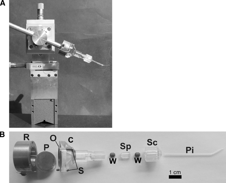
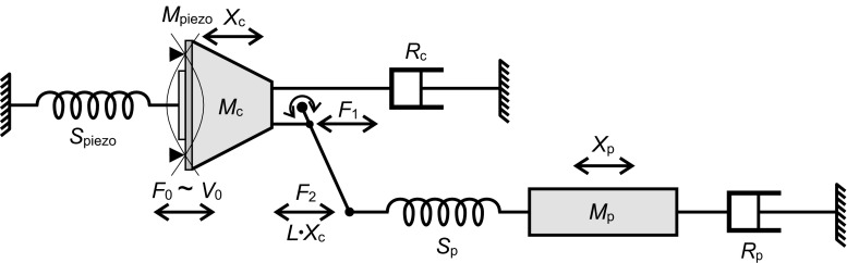
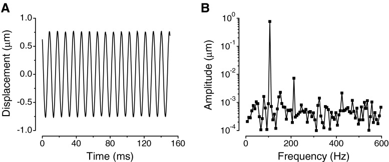
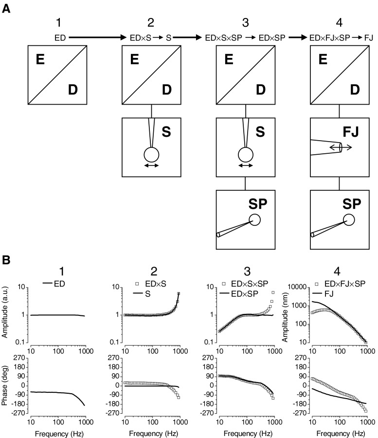
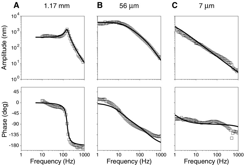
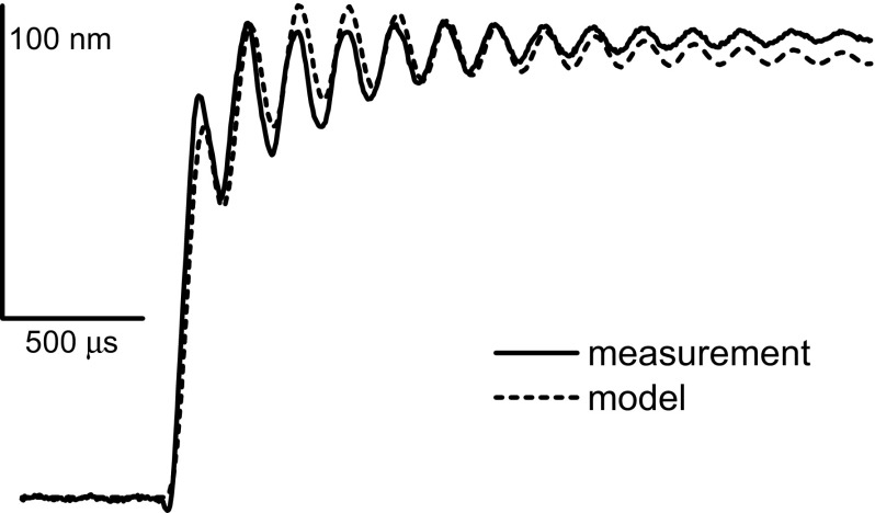
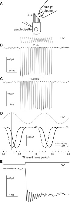
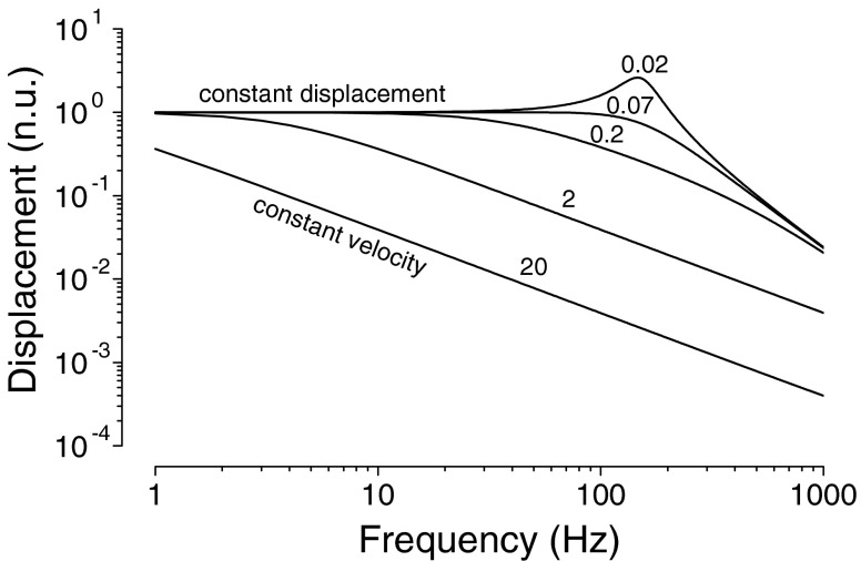
The investigation of small physiological mechano-sensory systems, such as hair cells or their accessory structures in the inner ear or lateral line organ, requires mechanical stimulus equipment that allows spatial manipulation with micrometer precision and stimulation with amplitudes down to the nanometer scale. Here, we describe the calibration of a microfluid jet produced by a device that was designed to excite individual cochlear hair cell bundles or cupulae of the fish superficial lateral line system. The calibration involves a precise definition of the linearity and time- and frequency-dependent characteristics of the fluid jet as produced by a pressurized fluid-filled container combined with a glass pipette having a microscopically sized tip acting as an orifice. A procedure is described that can be applied during experiments to obtain a fluid jet's frequency response, which may vary with each individual glass pipette. At small orifice diameters (<15 mum), the fluid velocity of the jet is proportional to the displacement of the piezoelectric actuator pressurizing the container's volume and is suitable to stimulate the hair bundles of sensory hair cells. With increasing diameter, the fluid jet velocity becomes proportional to the actuator's velocity. The experimentally observed characteristics can be described adequately by a dynamical model of damped fluid masses coupled by elastic components.


Figures

FIG. 1.
FIG. 1.
The fluid jet-producing device. A Picture of the assembled fluid jet-producing device mounted on an x,y,z-micromanipulator. B Disassembled device showing its separate parts: R Rear brass element, P piezoelectric disc, O o-ring, S screws, C Perspex container, W rubber cone washer, Sp Perspex spacer, Sc Perspex screw cap, Pi glass pipette. The calibration bar indicates 1 cm.
FIG. 2.
FIG. 2.
Mechanical model representation of the fluid jet-producing device. F 0 is the piezoelectrically induced force, proportional to the applied voltage, V 0. The piezoelectric element consists of a brass disc (dark gray) and a smaller ceramic plate. The spring, S piezo, and a resistive element, R c, together with the mass of the piezo, M piezo, and the mass of the container fluid, M c (cone-shaped), affect the fluid displacement amplitude, X c, in the Perspex container. The fluid displacement, X c, is amplified through a lever arm, with ratio L, into L·X c, which drives the fluid in the glass pipette. The same lever ratio applies to the forces F 1 and F 2. The displacement response of the fluid mass in the pipette, X p, is determined by the pipette’s spring, S p, the pipette’s tip resistive element, R p, and the mass of the pipette fluid, M p. X p is taken as a proportional measure of the displacement of the jet fluid.
FIG. 3.
FIG. 3.
Sense probe displacements induced by the fluid jet. A Sense probe displacement in response to a 106-Hz vibrational fluid jet stimulus as a function of time. An average of ten traces is shown. B Fast Fourier transform of the average waveform shown in A with a fundamental component at 106 Hz and a second harmonic component at 212 Hz, which is more than 40 dB less in amplitude than the fundamental component. Total harmonic distortion (THD) was calculated using formula image, where a 1 is the response amplitude at the fundamental frequency and a n is the amplitude of the nth harmonic component, as determined from the FFT calculated from the averaged waveform of measured sense probe responses.
FIG. 4.
FIG. 4.
Schematic representation of the fluid jet correction procedure. A Each column (1–4) represents a type of measurement needed to complete the correction. The frequency responses measured with the sense probe contain frequency-dependent properties of ED (equipment, demodulator), S (stimulus sphere), SP (sense probe), or FJ (fluid jet) as a function of frequency. Results represented in a column are used to correct the measured response in the next column, indicated by the long arrows and produce results pointed at with a short arrow. B Displacement amplitude and phase for each measurement (1–4) described in (A). Each solid line is the result of a correction (except for column 1) and is used in the next column to correct the measured frequency response (symbols), both for the amplitude and the phase response.
FIG. 5.
FIG. 5.
Effect of tip diameter on fluid jet response. Data points are the measured amplitude and phase responses as a function of frequency using a pipette without a tip restriction (A), a 56-μm tip (B), or a 7-μm tip (C). The solid lines are fits to the data with the model description (Eqs. 2a and 2b) of the jet-producing device (Fig. 2). Fixed parameters based on physical sizes and properties: L 1 = 7 mm; L 2 = 50 mm; D 1 = 13.4 mm; D 2 = 1.17 mm; ρ = 1,000 kg/m3. Fixed parameters: S piezo = 2.0 × 106 N/m; R c = 7 Ns/m. Varied parameters: A S p = 85 N/m, R p = 0.0165 Ns/m; F 0 = 7.0·10−3 N, (B) S p = 9 N/m, R p = 0.09 Ns/m; F 0 = 62·10-3 N, (C) S p = 11 N/m, R p = 2 Ns/m; F 0 = 52·10-3 N.
FIG. 6.
FIG. 6.
High frequency fluid jet resonance. Response of the fluid jet to an unfiltered step driver voltage applied to the piezoelectric disc, showing a high resonance frequency, f h = 5.65 kHz. (solid line, calibration as indicated). Parameters used in the model (dashed line): S piezo = 2.12 × 106 N/m; R c = 4 Ns/m; S p = 6.4 N/m, R p = 0.402 Ns/m; F 0 = 2.5 × 10−3 N.
FIG. 7.
FIG. 7.
Application of the fluid jet to excite sensory hair cells. A Schematic representation for recording transducer currents in cochlear outer hair cells. Indicated are the fluid jet’s pipette tip and the hair cell under whole-cell voltage-clamp configuration with a patch pipette at the lateral side. The sinusoidal driver voltage (DV) applied to the piezoelectric disc is indicated. Positive voltages correspond with the fluid moving out of the chamber towards the hair bundle so that it bends in the excitatory direction towards the tallest stereocilia. B Transducer currents in response to a fluid stimulus at 100 Hz. (C) Transducer currents in response to a fluid stimulus at 1,000 Hz from the same cell, and using the same fluid-jet pipette as in B. D Responses of transducer currents (dashed, 100 Hz; solid, 1,000 Hz) shown on an extended time axis in relation to two stimulus periods of the driver voltage (DV, thin black line upper trace). The two transducer currents have a comparable magnitude but show a different delay in activation with respect to the maxima of the driver voltage (vertical thin lines), which is caused by the different phase delays of the fluid jet at 100 and 1,000 Hz. The measured delays are 0.0194 and 0.171 periods, for respectively, the 100 Hz and the 1,000 Hz stimulus, and correspond to a phase delay of 7° and 62° respectively. E Step driver voltage (DV) applied to the piezoelectric disc of the device and the evoked transducer current showing a 5.65-kHz oscillation produced by resonance of the fluid in the Perspex container.
FIG. 8.
FIG. 8.
The effect of increasing pipette resistance. Series of modelled frequency responses showing fluid displacement output as a function of the frequency of the voltage signal put across the piezoelectric disc. Parameter values: L 1 = 7 mm; L 2 = 50 mm; D 1 = 13.4 mm; D 2 =  1.17 mm; ρ  = 1,000 kg/m3; S piezo = 2.0 × 106 N/m, R c = 7 Ns/m, S p = 55 N/m, values of pipette resistance (R p in Ns/m) are given next to each curve.

Similar articles

Cited by

References

    1. Assad JA, Corey DP. An active motor model for adaptation by vertebrate hair cells. J. Neurosci. 1992;12:3291–3309. - PMC - PubMed
    1. Benser ME, Marquis RE, Hudspeth AJ. Rapid, active hair bundle movements in hair cells from the bullfrog’s sacculus. J. Neurosci. 1996;16:5629–56431. - PMC - PubMed
    1. Beurg M, Evans MG, Hackney CM, Fettiplace R. A Large conductance calcium-selective mechanotransducer channel in mammalian cochlear hair cells. J. Neurosci. 2006;26:10992–11000. doi: 10.1523/JNEUROSCI.2188-06.2006. - DOI - PMC - PubMed
    1. Crawford AC, Fettiplace R. The mechanical properties of ciliary bundles of turtle cochlear hair cells. J. Physiol. 1985;364:359–379. - PMC - PubMed
    1. Denk W, Webb WW. Forward and reverse transduction at the limit of sensitivity studied by correlating electrical and mechanical fluctuations in frog saccular hair cells. Hear. Res. 1992;60:89–102. doi: 10.1016/0378-5955(92)90062-R. - DOI - PubMed

Publication types

LinkOut - more resources