. 2007 Apr;129(2):240-9.
doi: 10.1115/1.2486179.

Anisotropy of fibrous tissues in relation to the distribution of tensed and buckled fibers

Affiliations

Anisotropy of fibrous tissues in relation to the distribution of tensed and buckled fibers

Gerard A Ateshian. J Biomech Eng. 2007 Apr.

Abstract

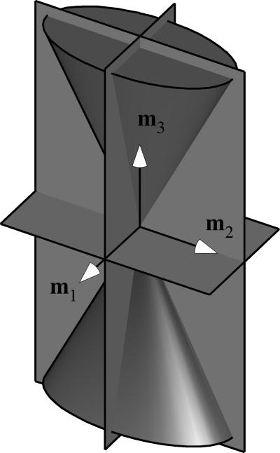
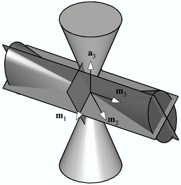
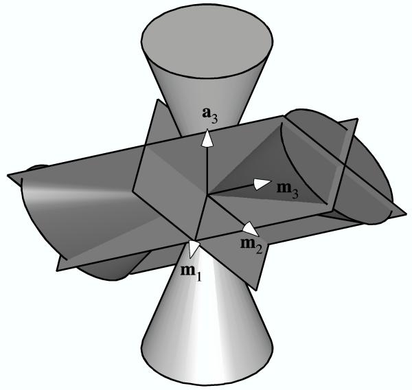
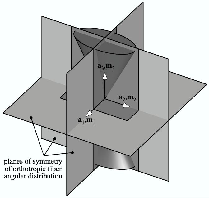
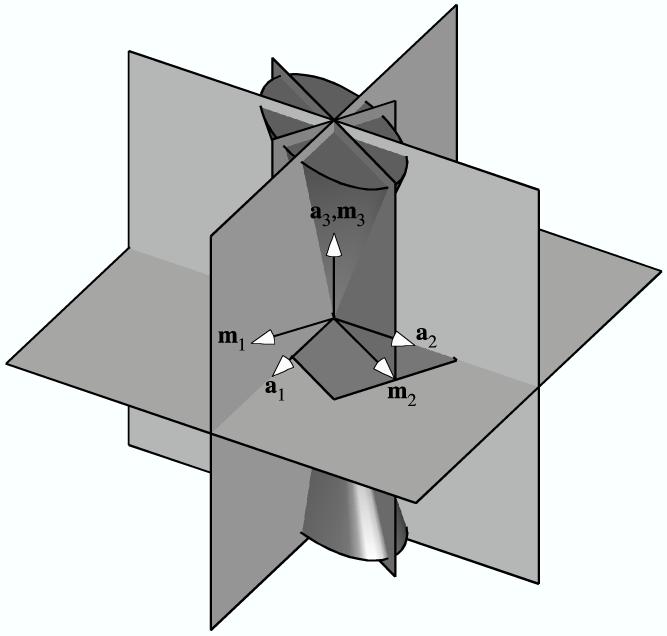
Fibrous tissues are characterized by a much higher stiffness in tension than compression. This study uses microstructural modeling to analyze the material symmetry of fibrous tissues undergoing tension and compression, to better understand how material symmetry relates to the distribution of tensed and buckled fibers. The analysis is also used to determine whether the behavior predicted from a microstructural model can be identically described by phenomenological continuum models. The analysis confirms that in the case when all the fibers are in tension in the current configuration, the material symmetry of a fibrous tissue in the corresponding reference configuration is dictated by the symmetry of its fiber angular distribution in that configuration. However, if the strain field exhibits a mix of tensile and compressive principal normal strains, the fibrous tissue is represented by a material body which consists only of those fibers which are in tension; the material symmetry of this body may be deduced from the superposition of the planes of symmetry of the strain and the planes of symmetry of the angular fiber distribution. Thus the material symmetry is dictated by the symmetry of the angular distribution of only those fibers which are in tension. Examples are provided for various fiber angular distribution symmetries. In particular, it is found that a fibrous tissue with isotropic fiber angular distribution exhibits orthotropic symmetry when subjected to a mix of tensile and compressive principal normal strains, with the planes of symmetry normal to the principal directions of the strain. This anisotropy occurs even under infinitesimal strains and is distinct from the anisotropy induced from the finite rotation of fibers. It is also noted that fibrous materials are not stable under all strain states due to the inability of fibers to sustain compression along their axis; this instability can be overcome by the incorporation of a ground matrix. It is concluded that the material response predicted using a microstructural model of the fibers cannot be described exactly by phenomenological continuum models. These results are also applicable to nonbiological fiber-composite materials.


Figures

Figure 1
Figure 1
Double elliptical cone of normal strain, shown with its three planes of symmetry.
Figure 2
Figure 2
The three planes of symmetry of the elliptical cone of normal strain in relation to planes of symmetry (not shown) of a transversely isotropic fiber angular distribution represented by a cone: (a) Example when all three planes coincide. (b) Alternate example when all three planes coincide. (c) Example of only one coincident plane (normal to m3). (d) Example of no coincident planes.
Figure 2
Figure 2
The three planes of symmetry of the elliptical cone of normal strain in relation to planes of symmetry (not shown) of a transversely isotropic fiber angular distribution represented by a cone: (a) Example when all three planes coincide. (b) Alternate example when all three planes coincide. (c) Example of only one coincident plane (normal to m3). (d) Example of no coincident planes.
Figure 3
Figure 3
The three planes of symmetry of the elliptical cone of normal strain (with unit normals {m1, m2, m3}) in relation to the three planes of symmetry of an orthotropic fiber angular distribution (with unit normals {a1, a2, a3}): (a) Example when all three planes coincide. (b) Example of only one coincident plane (normal to a3 and m3). (d) Example of no coincident planes.
Figure 3
Figure 3
The three planes of symmetry of the elliptical cone of normal strain (with unit normals {m1, m2, m3}) in relation to the three planes of symmetry of an orthotropic fiber angular distribution (with unit normals {a1, a2, a3}): (a) Example when all three planes coincide. (b) Example of only one coincident plane (normal to a3 and m3). (d) Example of no coincident planes.
Figure 4
Figure 4
Conical angle of fiber recruitment, ϕ0, versus λg/λf, for uniaxial loading of a bar of fibrous material with isotropic fiber angular distribution.
Figure 5
Figure 5
Tensile Young’s modulus for the example shown in Figure 4, normalized to EY=(923)λf45.
Figure 6
Figure 6
Apparent Poisson’s ratio ν = −E1/E3 = 1/ tan2 ϕ0 corresponding to Figure 4.

References

    1. Lanir Y. A structural theory for the homogeneous biaxial stress-strain relationships in flat collagenous tissues. J Biomech. 1979;12(6):423–36. - PubMed
    1. Lanir Y. Constitutive equations for fibrous connective tissues. J Biomech. 1983;16(1):1–12. - PubMed
    1. Humphrey JD, Yin FC. A new constitutive formulation for characterizing the mechanical behavior of soft tissues. Biophys J. 1987;52(4):563–70. - PMC - PubMed
    1. Soulhat J, Buschmann MD, Shirazi-Adl A. A fibril-network-reinforced biphasic model of cartilage in unconfined compression. J Biomech Eng. 1999;121(3):340–7. - PubMed
    1. Rigbi Z. Some thoughts concerning the existence or otherwise of an isotropic bimodulus material. J Eng Mater Technol. 1980;102:383–384.

Publication types