

Operational Characteristics of a 14-W 140-GHz Gyrotron for Dynamic Nuclear Polarization
- PMID: 17431442
- PMCID: PMC1851936
- DOI: 10.1109/TPS.2006.875776
Operational Characteristics of a 14-W 140-GHz Gyrotron for Dynamic Nuclear Polarization
Abstract
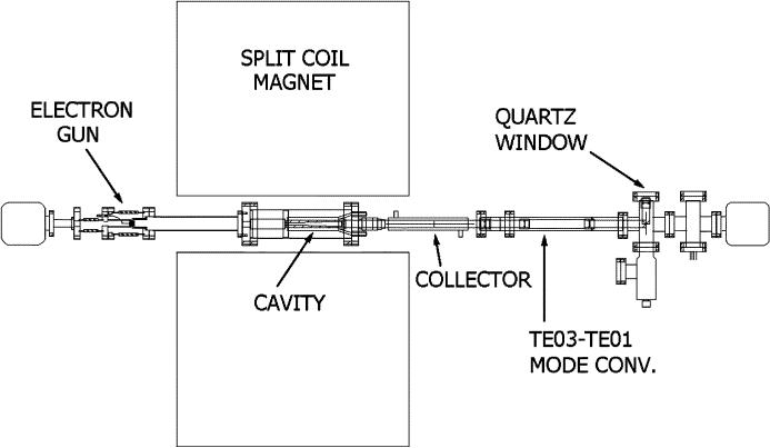
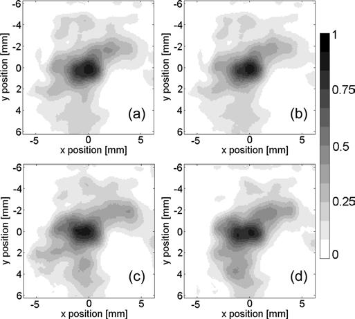
The operating characteristics of a 140-GHz 14-W long pulse gyrotron are presented. The device is being used in dynamic nuclear polarization enhanced nuclear magnetic resonance (DNP/NMR) spectroscopy experiments. The gyrotron yields 14 W peak power at 139.65 GHz from the TE(0,3) operating mode using a 12.3-kV 25-mA electron beam. Additionally, up to 12 W peak has been observed in the TE(2,3) mode at 136.90 GHz. A series of mode converters transform the TE(0,3) operating mode to the TE(1,1) mode. Experimental results are compared with nonlinear simulations and show reasonable agreement. The millimeter-wave output beam was imaged in a single shot using a pyroelectric camera. The mode patterns matched reasonably well to theory for both the TE(0,1) mode and the TE(1,1) mode. Repeatable mode patterns were obtained at intervals ranging from 0.8 s apart to 11 min apart at the output of the final mode converter.
Figures


References
-
- Wind RA, et al. Applications of dynamic nuclear polarization in 13C NMR in solids. Progress NMR Spectroscopy. 1985;17:33–67.
-
- Becerra LR, Gerfin GJ, Temkin RJ, Singel DJ, Griffin RG. Dynamic nuclear polarization with a cyclotron resonance maser at 5 Tesla. Phys. Rev. Lett. 1993;117:3561–3564. - PubMed
-
- Kreischer KE, Farrar C, Griffin R, Temkin R. The use of a 250 GHz gyrotron in a DNP/NMR spectrometer; Proc. 23rd Int. Conf. Infrared Millim. Waves; 1998. pp. 341–357.
-
- Idehara T, Ogawa I, Mitsudo S, Pereyaslavets M, Nishida N, Yoshida K. Development of a frequency tunable, medium power gyrotron (gyrotron FU series) as submillimeter wave radiation sources. IEEE Trans. Plasma Sci. 1999 Apr.27(2):340–354.
-
- Hornstein MK, Bajaj VS, Griffin RG, Kreischer KE, Mastovsky I, Shapiro MA, Sirigiri JR, Temkin RJ. Second harmonic operation at 460 GHz and broadband continuous frequency tuning of a gyrotron oscillator. IEEE Trans. Electron Devices. 2005 May;52(5):798–807.
Grants and funding
LinkOut - more resources
Full Text Sources