

Review
doi: 10.1098/rsta.2005.1687.
Supercritical carbon dioxide: putting the fizz into biomaterials
Affiliations
- PMID: 17464360
- PMCID: PMC1855442
- DOI: 10.1098/rsta.2005.1687
Item in Clipboard
Review
Supercritical carbon dioxide: putting the fizz into biomaterials
Philos Trans A Math Phys Eng Sci.
.
Abstract
This paper describes recent progress made in the use of high pressure or supercritical fluids to process polymers into three-dimensional tissue engineering scaffolds. Three current examples are highlighted: foaming of acrylates for use in cartilage tissue engineering; plasticization and encapsulation of bioactive species into biodegradable polyesters for bone tissue engineering; and a novel laser sintering process used to fabricate three-dimensional biodegradable polyester structures from particles prepared via a supercritical route.
Figures
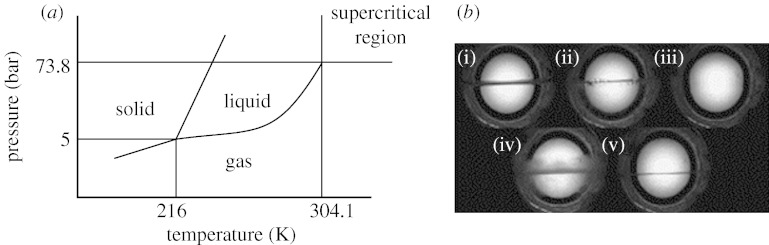
(a) Phase diagram for carbon dioxide, showing critical point and supercritical region (McHugh & Krukonis 1994). (b) A practical demonstration showing the creation of the single supercritical fluid phase (image (iii)) by taking liquid CO2 above its critical temperature and pressure (images (i) and (ii)); with subsequent lowering of temperature (and hence pressure) the process is reversed (images (iv) and (v)) (Quirk et al. 2004; Howdle 2004).

The in situ plasticization and foaming of amorphous polymers. Images are taken through a high-pressure vessel with a sapphire window. This plasticization and foaming can occur via two routes. The first route is shown in images (a)–(c), the polymer, although plasticized, remains structurally unchanged until nearly all the carbon dioxide gas has been vented and then the polymer foams. In these images, the internal diameter of the vessel has been restricted by the incorporation of a graduated scale (mm markings) (Barry et al. in press a). The second route is shown in images (d)–(f), the polymer powder is plasticized forming a polymer gas solution which foams when all the carbon dioxide gas has been vented (Quirk et al. 2004).

Chondrocytes growing on the unfoamed (a,c) and foamed (b,d) PEMA/THFMA substrates. From Barry et al. (2004).

Micro-CT images of scaffolds processed at different rates. (a) Rapid depressurization (30 s for 100 bar to ambient pressure). (b) Slow depressurization (60 min for 100 bar to ambient pressure). Changes in porosity, pore size and interconnectivity are clearly visible from the images. Images from Barry et al. (in press a).

Compressive stress–strain behaviour for SIS/THFMA blend. For comparison, PEMA/THFMA prepared by the same protocol is included. It can be seen that the behaviour of these materials following compression is very different. Damage to the PEMA/THFMA foams occurs at the onset of the plateau and results in densification and ultimately the complete destruction of the foam. This is not the case for the SIS/THFMA, whereby removal of the stress allows the recovery of the material. Inset; electron micrographs of a foamed SIS/THFMA (30%/70%) disc. From Barry et al. (in press b).

PLA scaffolds. (a) The scaffolds as fabricated and removed from the Teflon mould. (b) Micro-CT images of the scaffolds, and (c,d) SEM images demonstrating that variation of temperature, pressure and venting rate leads to scaffolds with different pore architectures. From Quirk et al. (2004).

(a) Schematic diagram for the supercritical fluid apparatus used to prepare PDLLA particles: A, CO2 cylinder; B, nitrogen cylinder; C, CO2 feed pump; D, valves; E, mixing vessel; F, collecting chamber; G, pressure gauges; H, thermocouple; I, backpressure regulator; J, cooling device; K, spraying (ball) valve; L, cone nozzle (Hao et al. 2004). (b) SEM images of P(DLLA) particles (Whitaker et al. 2005). (c) Schematic diagram of experimental SLS set-up. 1, diode laser; 2, quartz fibre; 3, X–Y plotter; 4, polymer powder; 5, powder container with precision elevator piston (Z-axis) (Antonov et al. 2005). (d) PLA scaffold made using the sintering process described in text.
References
-
- Alavi S.H., Gogoi B.K., Khan M., Bowman B.J., Rizvi S.S.H.Food Res. Int 321999107–118. 10.1016/S0963-9969(99)00063-0. - DOI
-
- Arora K.A., Lesser A.J., McCarthy T.J.Macromolecules 3119984614–4620. 10.1021/ma971811z. - DOI
-
- Barry J.J.A., Silva M.M.C.G., Shakesheff K.M., Howdle S.M., Alexander M.R.Adv. Funct. Mater 1520051134–1140. 10.1002/adfm.200400562. - DOI
Publication types
MeSH terms
Substances
Grants and funding
LinkOut - more resources
Full Text Sources
Other Literature Sources