. 2007 Aug;33(8):1277-84.
doi: 10.1016/j.ultrasmedbio.2007.02.004. Epub 2007 May 3.

Real-time 3-d intracranial ultrasound with an endoscopic matrix array transducer

Affiliations

Real-time 3-d intracranial ultrasound with an endoscopic matrix array transducer

Edward D Light et al. Ultrasound Med Biol. 2007 Aug.

Abstract

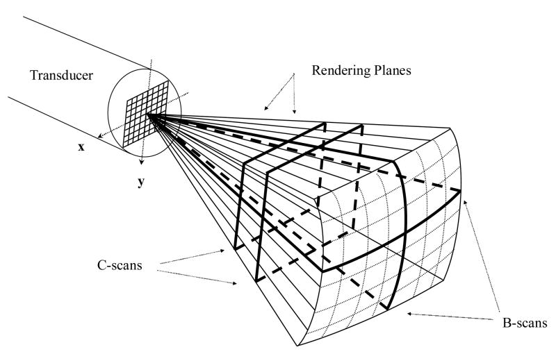
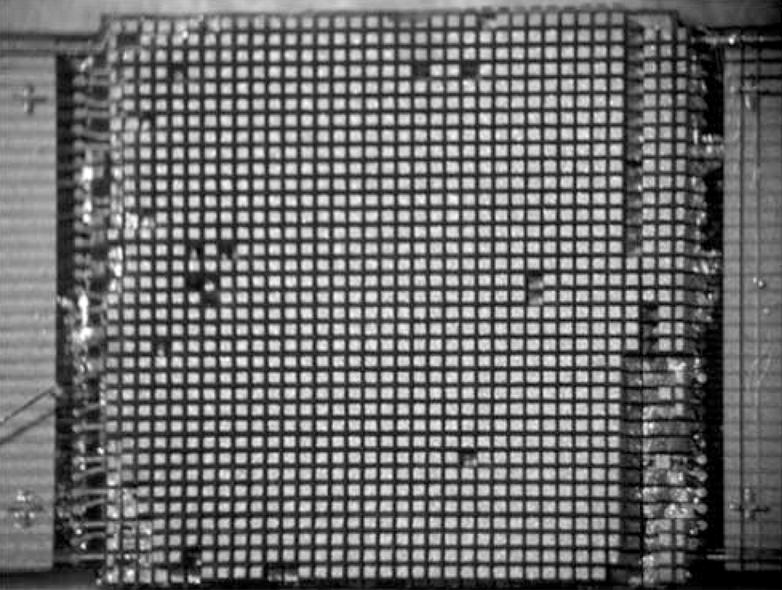
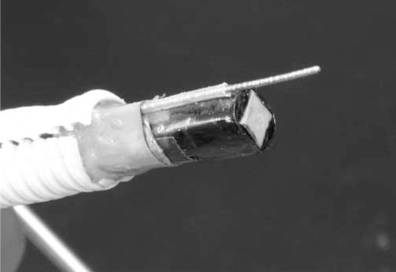
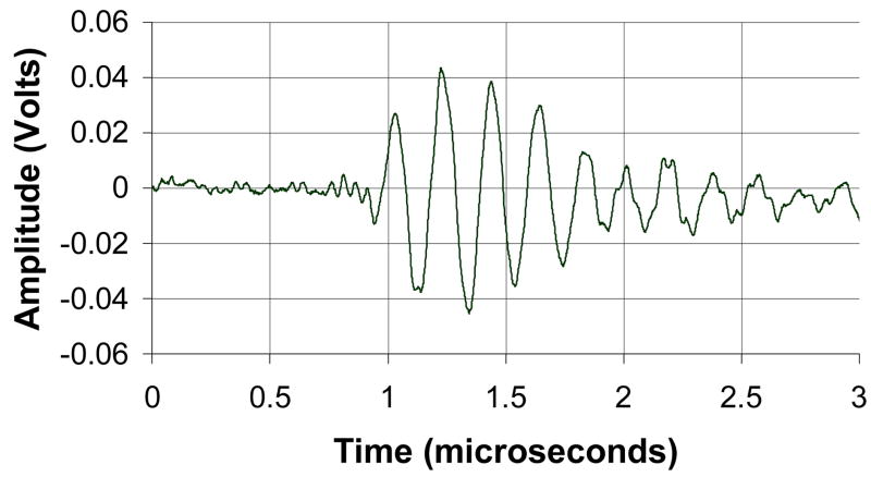
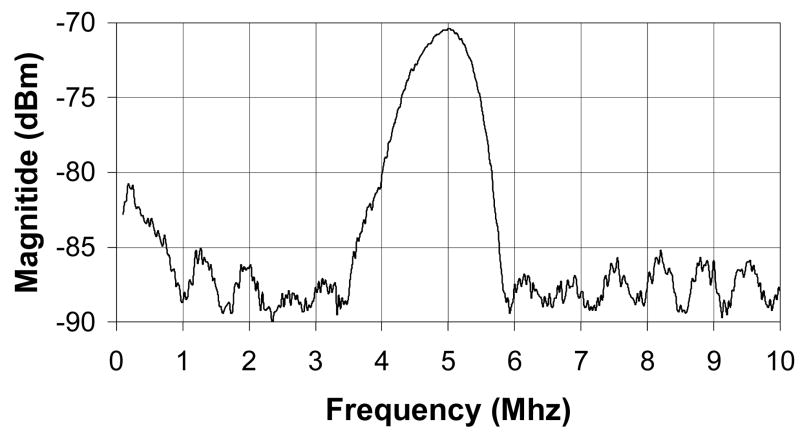
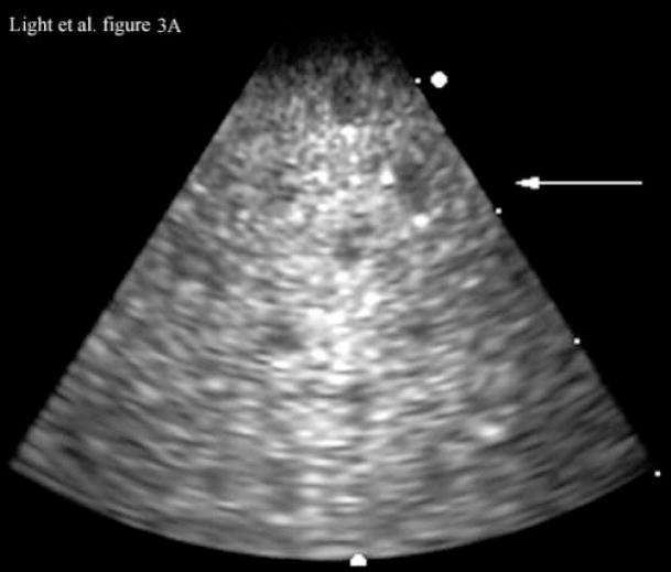
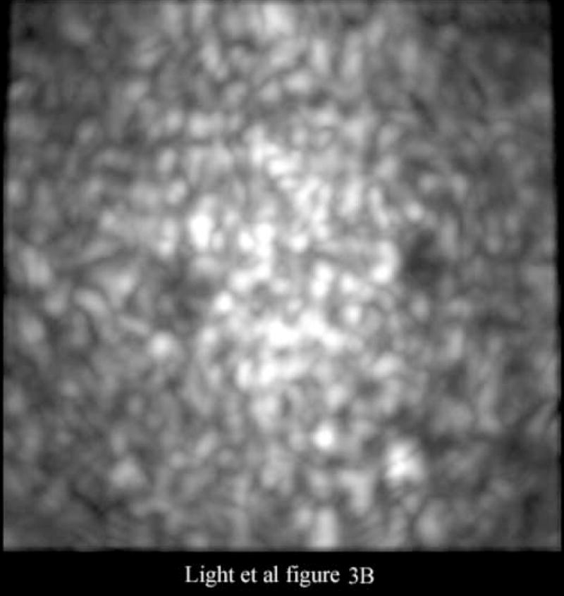
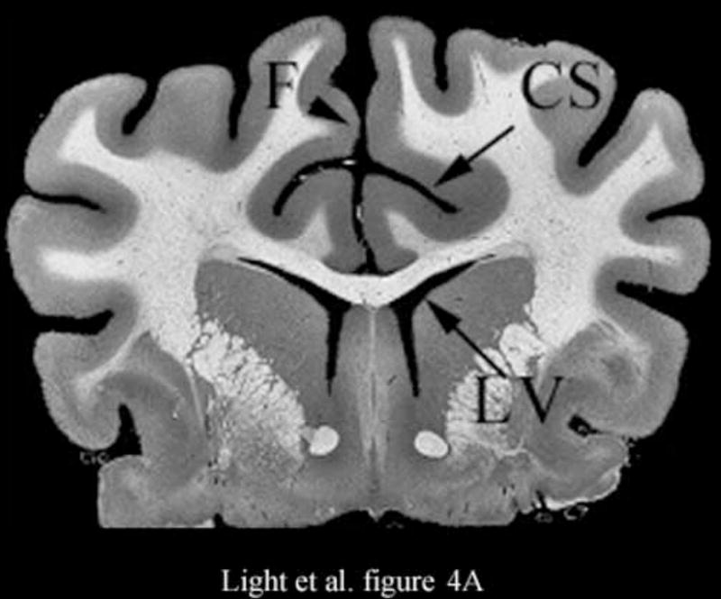
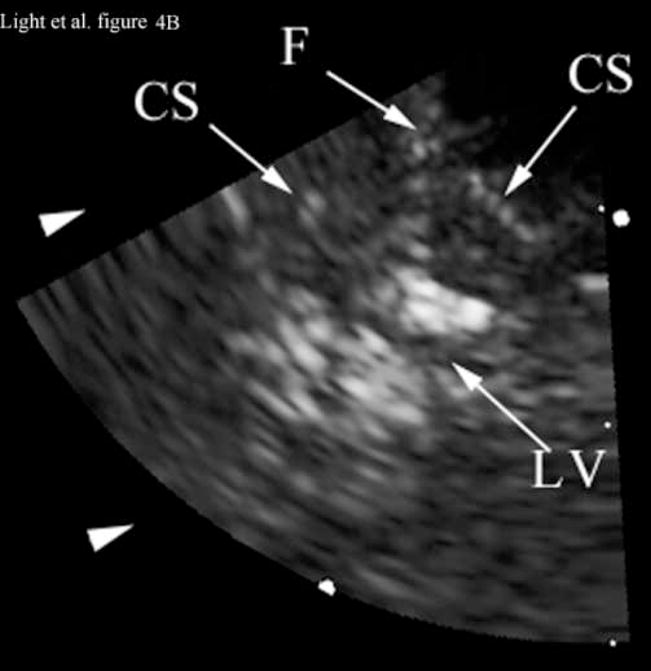
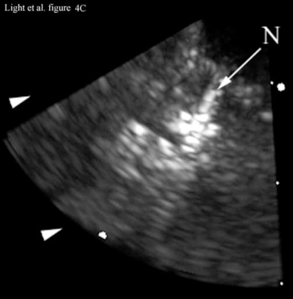
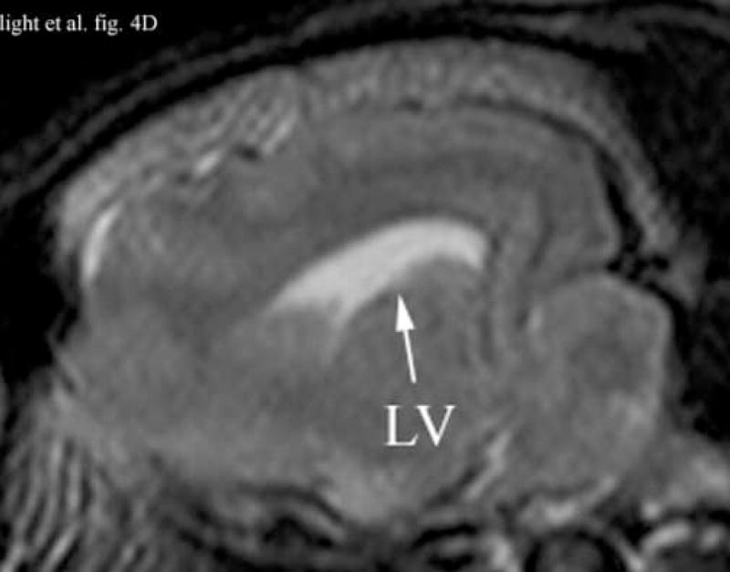
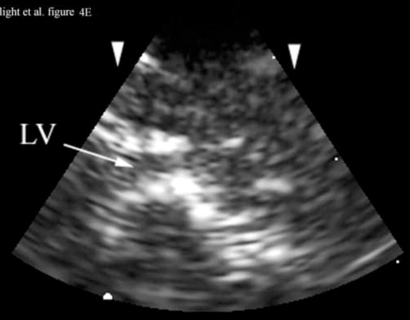
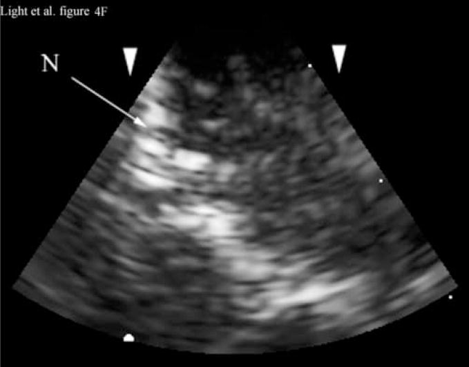
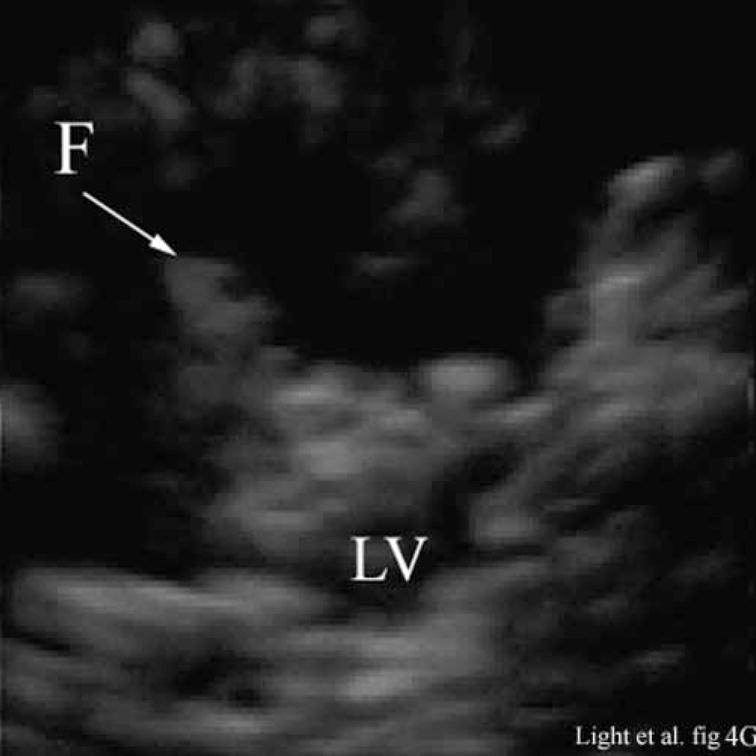
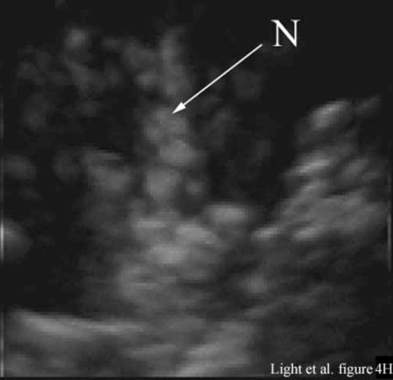
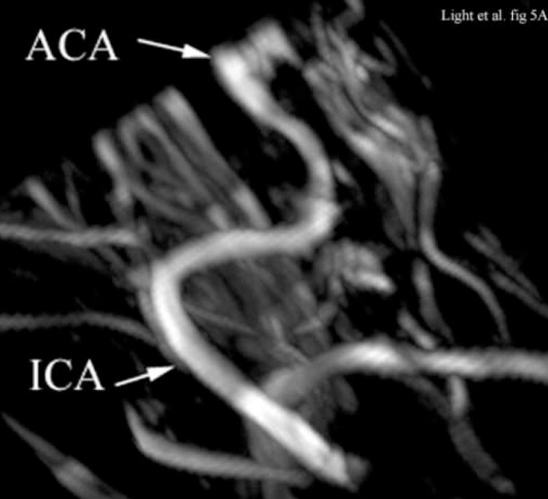
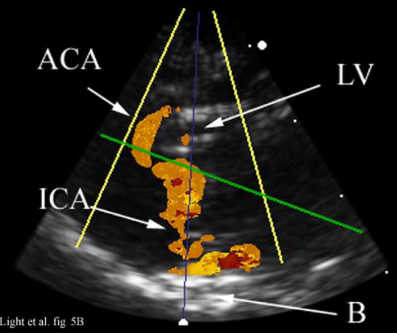
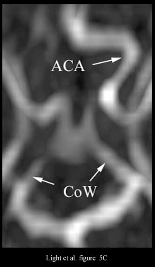
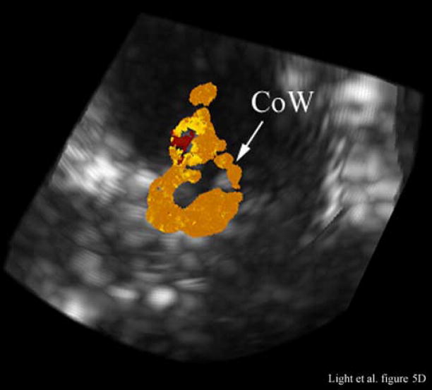
A transducer originally designed for transesophageal echocardiography (TEE) was adapted for real-time volumetric endoscopic imaging of the brain. The transducer consists of a 36 x 36 array with an interelement spacing of 0.18 mm. There are 504 transmitting and 252 receive channels placed in a regular pattern in the array. The operating frequency is 4.5 MHz with a -6 dB bandwidth of 30%. The transducer is fabricated on a 10-layer flexible circuit from Microconnex (Snoqualmie, WA, USA). The purpose of this study is to evaluate the clinical feasibility of real-time 3-D intracranial ultrasound with this device. The Volumetrics Medical Imaging (Durham, NC, USA) 3-D scanner was used to obtain images in a canine model. A transcalvarial acoustic window was created under general anesthesia in the animal laboratory by placing a 10-mm burr hole in the high parietal calvarium of a 50-kg canine subject. The burr-hole was placed in a left parasagittal location to avoid the sagittal sinus, and the transducer was placed against the intact dura mater for ultrasound imaging. Images of the lateral ventricles were produced, including real-time 3-D guidance of a needle puncture of one ventricle. In a second canine subject, contrast-enhanced 3-D Doppler color flow images were made of the cerebral vessels including the complete Circle of Willis. Clinical applications may include real-time 3-D guidance of cerebrospinal fluid extraction from the lateral ventricles and bedside evaluation of critically ill patients where computed tomography and magnetic resonance imaging techniques are unavailable.


Figures

Figure 1
Figure 1
Schematic of the pyramidal scan from a 2D array transducer. Bold lines indicate possible display planes. By integrating and spatially filtering between two user-selected planes, real-time 3D rendered images are displayed.
Figure 2
Figure 2
Transducer photos and typical pulse and spectrum from the transducer are shown. Figure 2A is a close up of diced 5 MHz matrix array transducer for intracrannial brain imaging. The total aperture size is 6.48 × 6.48 mm. Figure 2B is a photograph of completed matrix array transducer showing working port and a Brockenbrough needle coming out of the port. Figures 2C and 2D show typical pulse and spectrum from the transducer pictured in figure 2A and 2B. The center frequency is 4.5 MHz and the −6 dB fractional bandwidth is 30%.
Figure 2
Figure 2
Transducer photos and typical pulse and spectrum from the transducer are shown. Figure 2A is a close up of diced 5 MHz matrix array transducer for intracrannial brain imaging. The total aperture size is 6.48 × 6.48 mm. Figure 2B is a photograph of completed matrix array transducer showing working port and a Brockenbrough needle coming out of the port. Figures 2C and 2D show typical pulse and spectrum from the transducer pictured in figure 2A and 2B. The center frequency is 4.5 MHz and the −6 dB fractional bandwidth is 30%.
Figure 3
Figure 3
Figure 3A is a 4 cm deep B-scan, and Figure 3B is the corresponding real-time C-scan made at the plane indicated by the arrow. The lesions are 4 mm in diameter.
Figure 3
Figure 3
Figure 3A is a 4 cm deep B-scan, and Figure 3B is the corresponding real-time C-scan made at the plane indicated by the arrow. The lesions are 4 mm in diameter.
Figure 4
Figure 4
Figure 4A shows a coronal anatomical slice through the canine brain. The falx (F), cingulate sulcus (CS) and one of the lateral ventricles (LV) are labeled. Figure 4B shows a 3 cm deep B-mode image of the coronal plane also showing the Falx (F), cingulated sulcus (CS) and lateral ventricle (LV) prior to the LV being punctured by a needle. The needle (N) is viewed in Figure 4C after insertion. Figure 4D is an MRI of a para-sagittal plane through a lateral ventricle of a different canine brain. The lateral ventricle (LV) is white in the MRI image. Figure 4E shows the simultaneous orthogonal B-scan to Figure 4B. Again, we see the LV before the needle is inserted. Figure 4F shows the same B-scan plane with the needle (N) inserted into the LV. This plane was obtained simultaneously with Figure 4C and is orthogonal to Figure 4C. Figure 4G is the simultaneous real-time rendered view of the LV before the needle is inserted. We also see the Falx (F) in this image. Figure 4H, displayed simultaneously with Figure 4C and 4F, shows the needle (N) after being inserted into the LV.
Figure 4
Figure 4
Figure 4A shows a coronal anatomical slice through the canine brain. The falx (F), cingulate sulcus (CS) and one of the lateral ventricles (LV) are labeled. Figure 4B shows a 3 cm deep B-mode image of the coronal plane also showing the Falx (F), cingulated sulcus (CS) and lateral ventricle (LV) prior to the LV being punctured by a needle. The needle (N) is viewed in Figure 4C after insertion. Figure 4D is an MRI of a para-sagittal plane through a lateral ventricle of a different canine brain. The lateral ventricle (LV) is white in the MRI image. Figure 4E shows the simultaneous orthogonal B-scan to Figure 4B. Again, we see the LV before the needle is inserted. Figure 4F shows the same B-scan plane with the needle (N) inserted into the LV. This plane was obtained simultaneously with Figure 4C and is orthogonal to Figure 4C. Figure 4G is the simultaneous real-time rendered view of the LV before the needle is inserted. We also see the Falx (F) in this image. Figure 4H, displayed simultaneously with Figure 4C and 4F, shows the needle (N) after being inserted into the LV.
Figure 5
Figure 5
Figure 5A shows an illustrative MRA of the internal carotid artery (ICA) and anterior cerebral artery (ACA) from a different canine. The para-sagittal plane, Figure 5B, shows a 4 cm deep B-scan that is 7.4 mm thick. The contrast enhanced image shows the ICA, skull base (B), ACA and one of the LV’s. The Circle of Willis (CoW) with the ACA coming off is shown in the second MRA image (Figure 5C). The CoW is also seen in the axial plane of the simultaneous real-time C-scan (Figure 5D). This C-scan is 9.9 mm thick.
Figure 5
Figure 5
Figure 5A shows an illustrative MRA of the internal carotid artery (ICA) and anterior cerebral artery (ACA) from a different canine. The para-sagittal plane, Figure 5B, shows a 4 cm deep B-scan that is 7.4 mm thick. The contrast enhanced image shows the ICA, skull base (B), ACA and one of the LV’s. The Circle of Willis (CoW) with the ACA coming off is shown in the second MRA image (Figure 5C). The CoW is also seen in the axial plane of the simultaneous real-time C-scan (Figure 5D). This C-scan is 9.9 mm thick.

References

    1. Black PMcL, Moriarty T, Alexander E, III, et al. Development and implementation of intraoperative magnetic resonance imaging. Neurosurgery. 1997;41:831–845. - PubMed
    1. Brunke SS, Lockwood GR. Broad-bandwidth radiation patterns of sparse two-dimensional vernier arrays. IEEE Trans Ultrason Ferro and Freq Control. 1997;44:1101–1109.
    1. Commeau RM, Sadikot AF, Fenster A, Peters TM. Intraoperative ultrasound for guidance and tissue shift correction in image-guided neurosurgery. Medical Physics. 2000;27:787–800. - PubMed
    1. Fletcher TF. Canine brain atlas. http://vanat.cvm.umn.edu:16080/brainsect/index.html.
    1. Hansen C, Wilkening W, Ermert H. Intraoperative contrast enhanced perfusion imaging of cerebral tumors. Proceedings IEEE Trans Ultrason Symp. 2005:743–746.

Publication types

MeSH terms