

doi: 10.1186/1749-799X-2-7.
Experimental and analytical validation of a modular acetabular prosthesis in total hip arthroplasty
Affiliations
- PMID: 17506882
- PMCID: PMC1891272
- DOI: 10.1186/1749-799X-2-7
Item in Clipboard
Experimental and analytical validation of a modular acetabular prosthesis in total hip arthroplasty
J Orthop Surg Res.
.
Abstract
A finite element model has been developed to predict in vivo micro motion between a modular acetabular cup and liner after cement less total hip arthroplasty. The purpose of this study is to experimentally validate the model. Six LVDT sensors were used to monitor the micromotion of the liner when subjected to loading conditions ranging from 250 N to 5000 N. Deformations at points of interest for both the experiment and FEM were compared. Results of the FEM with different coefficient of friction between the liner and the cup were investigated to correlate with the experimental results.
Figures
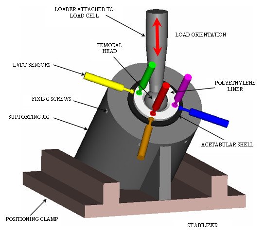
Experiment set-up. Orientation of the acetabular components (acetabular shell, liner and femoral head) with respect to applied load.
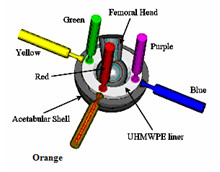
Modular Acetabular components set-up and LVDT sensors' positioning.
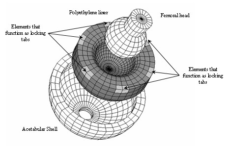
Finite Element Model of the acetabular shell, liner and femoral head. The liner locking mechanism was simulated constraining all degrees of freedom of the nodes located at the same positions as locking tabs of the real-life liner.
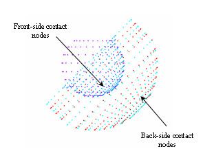
Contacting areas (Acetabular Shell/liner and Liner/femoral head) involved in the Finite Element Model.
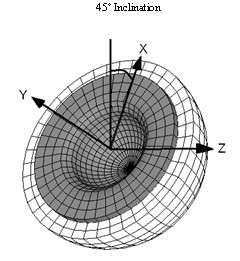
Coordinate system used as a reference for the loads in the FE model. The CS is shown with respect to the acetabular shell inclination angle.
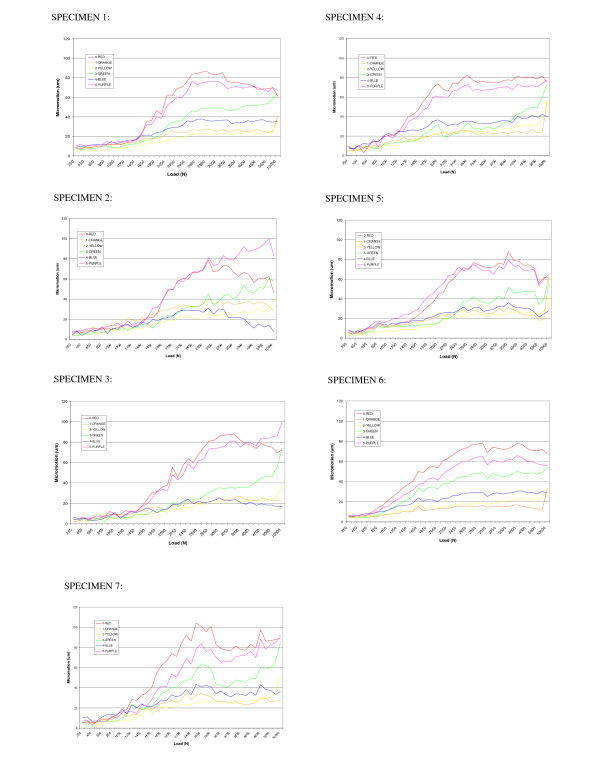
Maximum micromotions achieved for each of the seven liner specimen analyzed.
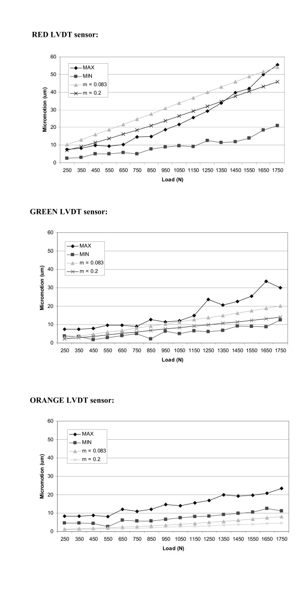
Maximum and minimum micromotions values, among all the specimens analyzed, recorded for each sensor. Comparison with the results obtained with the FE model considering two different friction coefficients.
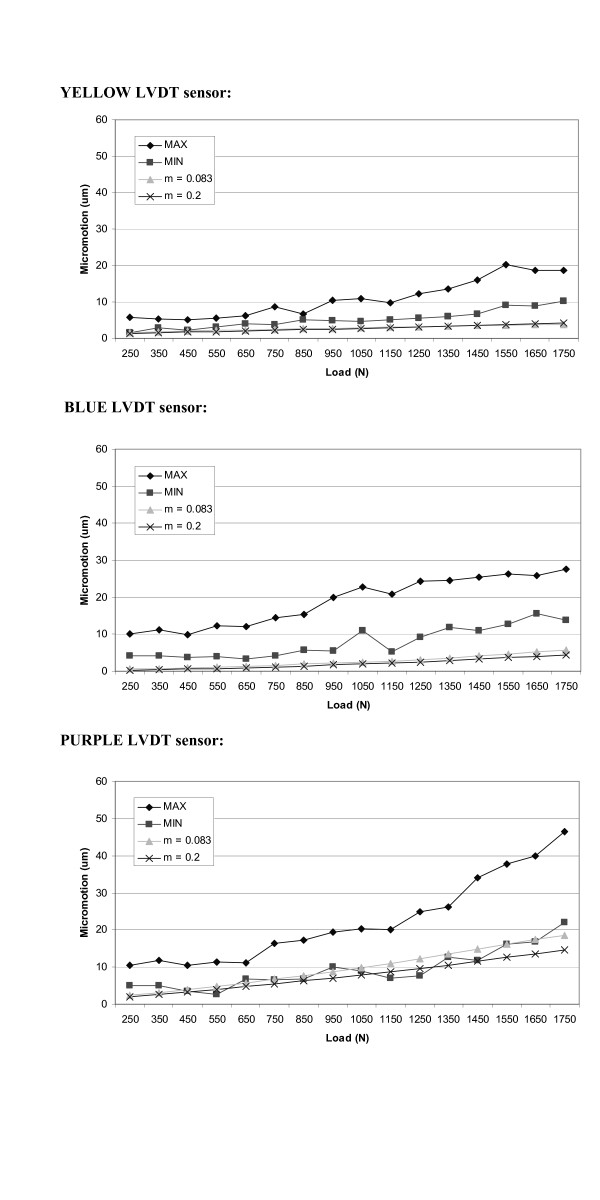
Maximum and minimum micromotions values, among all the specimens analyzed, recorded for each sensor. Comparison with the results obtained with the FE model considering two different friction coefficients.
Similar articles
-
Study of micromotion in modular acetabular components during gait and subluxation: a finite element investigation.J Biomech Eng. 2008 Apr;130(2):021002. doi: 10.1115/1.2898715. J Biomech Eng. 2008. PMID: 18412489
-
The influence of head diameter and wall thickness on deformations of metallic acetabular press-fit cups and UHMWPE liners: a finite element analysis.J Orthop Sci. 2013 Mar;18(2):264-70. doi: 10.1007/s00776-012-0340-7. Epub 2013 Feb 3. J Orthop Sci. 2013. PMID: 23377753
-
Failure analysis of a ceramic bearing acetabular component.J Bone Joint Surg Am. 2007 Feb;89(2):367-75. doi: 10.2106/JBJS.F.00148. J Bone Joint Surg Am. 2007. PMID: 17272452
-
Dissociation of the S-ROM metal-backed polyethylene acetabular liner--a case report and literature review.Acta Orthop Belg. 2003;69(1):86-8. Acta Orthop Belg. 2003. PMID: 12666298 Review.
-
Review of the evolution of the cementless acetabular cup.Orthopedics. 2008 Dec;31(12 Suppl 2):orthosupersite.com/view.asp?rID=37178. Orthopedics. 2008. PMID: 19298028 Review.
Cited by
-
Contact mechanics of modular metal-on-polyethylene total hip replacement under adverse edge loading conditions.J Biomech. 2014 Oct 17;47(13):3303-9. doi: 10.1016/j.jbiomech.2014.08.015. Epub 2014 Sep 1. J Biomech. 2014. PMID: 25218504 Free PMC article.
-
Head, acetabular liner composition, and rate of revision and wear in total hip arthroplasty: a Bayesian network meta-analysis.Sci Rep. 2023 Nov 21;13(1):20327. doi: 10.1038/s41598-023-47670-z. Sci Rep. 2023. PMID: 37989863 Free PMC article.
-
In vitro and in silico methods for the biomechanical assessment of osseointegrated transfemoral prostheses: a systematic review.Front Bioeng Biotechnol. 2023 Aug 17;11:1237919. doi: 10.3389/fbioe.2023.1237919. eCollection 2023. Front Bioeng Biotechnol. 2023. PMID: 37662439 Free PMC article. Review.
References
-
- Mow VC, Hayes WC. Basic Orthopedics Biomechanics. Vol. 11. Lippincott-Raven Publishers, Philadelphia; 1997. pp. 395–460.
-
- Charnley J. Low Friction Arthroplasty of the Hip: Theory and Practice. Springer, Berlin; 1979.
-
- Barrack RL, Folgueras A, Munn B, Tvetden D, Sharkey P. "Pelvis Lysis and Polyethylene Wear at 5–8 Years in an Uncemented Total Hip". Clinical Orthopeadics. 1997;335:211–217. - PubMed
-
- Dowdy PA, Rorabeck CH, Bourne RB. "Uncemented total hip arthroplasty in patients 50 years of age or younger". Journal of Biomechanics. 1997;12:853–862. - PubMed
-
- Schamalzried TP, Guttmann D, Grecula M, Amstutz HC. "The relationship between the design, position and articular wear of acetabular components inserted without cement and the development of pelvic osteolysis". Journal of Bone Joint Surgery American. 1994;76:677–688. - PubMed
LinkOut - more resources
Full Text Sources
Other Literature Sources
