. 2007 Jun-Jul;28(6):1036-41.
doi: 10.3174/ajnr.A0500.

Investigating sacroplasty: technical considerations and finite element analysis of polymethylmethacrylate infusion into cadaveric sacrum

Affiliations

Investigating sacroplasty: technical considerations and finite element analysis of polymethylmethacrylate infusion into cadaveric sacrum

C T Whitlow et al. AJNR Am J Neuroradiol. 2007 Jun-Jul.

Abstract

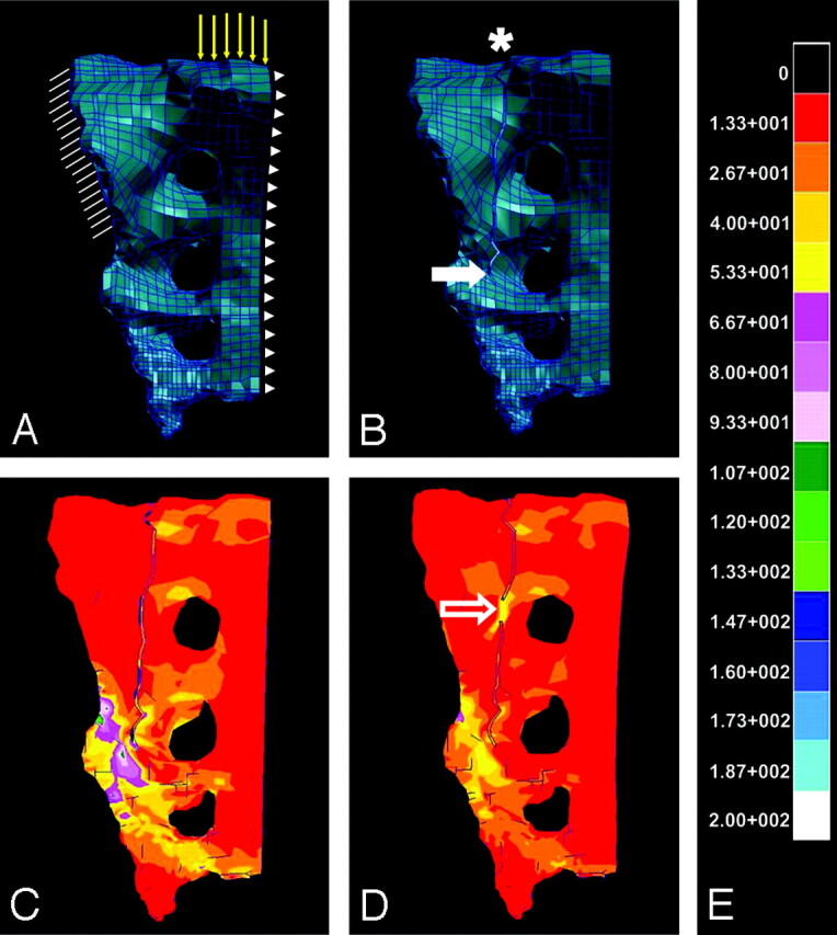
Background and purpose: Sacroplasty is not as routinely performed as vertebroplasty, possibly due to technical challenges and the paucity of data regarding subsequent outcomes. The first goal of the present investigation was to describe a technique for sacroplasty that facilitates safe needle placement and polymethylmethacrylate (PMMA) extrusion. The second goal was to perform finite element analysis (FEA) by using a geometric model of sacral fracture to identify mechanical outcomes of sacroplasty.

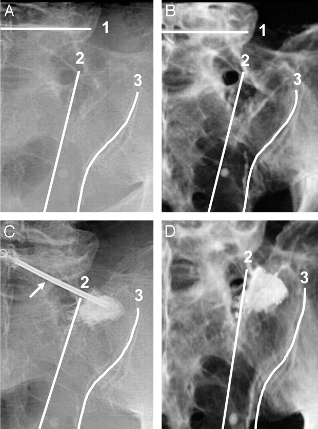
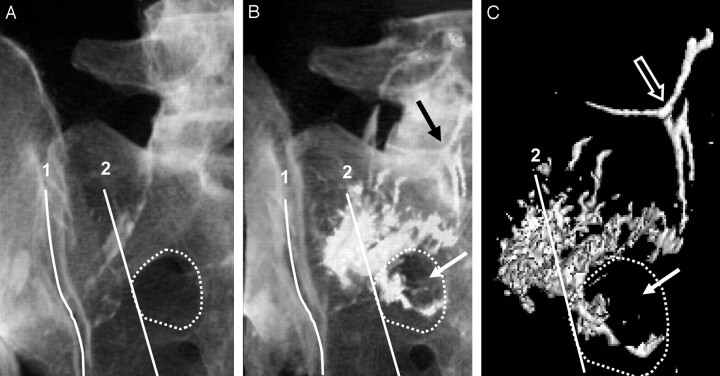
Materials and methods: Sacroplasty was performed on fresh pelvis specimens (n=4) under biplane fluoroscopy. Cadavers were imaged via CT before and after sacroplasty and volume rendered to examine needle placement and PMMA extrusion. The volume-rendered CT data were then used to generate geometric models of the intact, fractured, and cement-augmented fractured sacrum for comparison by using FEA.

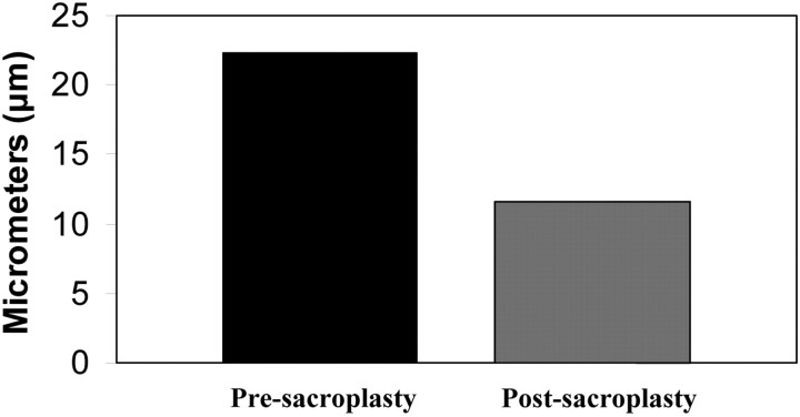
Results: CT data demonstrate that safe injection needle placement and PMMA delivery may be facilitated by orienting the needle parallel to the L5-S1 interspace and ipsilateral sacroiliac joint, then targeting the superolateral sacral ala within an area bounded by a line lateral to the posterior foraminal openings and a line superimposed on the medial edge of the sacroiliac joint. FEA revealed that simulated sacroplasty decreased maximal principal stress at the point of sacral fracture propagation by 83% and fracture gap micromotion by 48%.

Conclusion: Sacral landmarks can be used to place PMMA safely where sacral fractures occur. FEA suggests that sacroplasty may decrease fracture-associated mechanical stress and micromotion, which may contribute to patient reports of decreased pain and increased mobility postsacroplasty.


Figures

Fig 1.
Fig 1.
Intact (A) and fractured (B) FEMs of a hemisacrum are shown, which were constructed by using densitometric CT data from a single imaged cadaveric pelvis. In the models (A, B), a system of individual elements interconnected by a meshwork of discrete nodes has been assigned elasticity parameters approximating that of bone. Boundary and loading conditions applied to the intact sacral fracture and cement-augmented sacral fracture models are demonstrated (A). Hatch marks (A) represent boundary conditions that were applied to simulate anchoring of the sacrum at the sacroiliac joint. Yellow vector lines (A) indicate loading conditions, which were defined as a 35-kg force, approximating one half of body weight above the first sacral vertebra. Arrowheads (A) demonstrate the sagittal plane along which movement could occur in a 1-legged-stance paradigm. An asterisk and solid arrow (B) indicate sacral fracture origin and the point of fracture propagation, respectively. Color-coded transformation of FEA data demonstrates the amount of maximal principal stress experienced by the hemisacrum after the application of a 35-kg load, both before (C) and after (D) fusion at a point along the fracture (open arrow) designed to simulate sacroplasty. Each color represents kilopascals of maximal principal stress according to the calibration scale provided (E), with red corresponding to the lowest and white corresponding to the highest levels of maximal principal stress. Note that the point of fracture fusion (open arrow, D) appears to subsume a portion of the stress generated by the 35-kg load, thereby attenuating maximal principal stress that surrounds the site of fracture propagation, as compared with the prefusion model (C).
Fig 2.
Fig 2.
Fluoroscopic (A, C) and corresponding volume-rendered 3D reconstructions of CT images (B, D) of a hemisacrum from a single cadaveric pelvis, demonstrating anatomic landmarks for needle placement (arrow in image C indicates needle) and PMMA injection before (A, B) and after (C, D) sacroplasty. The sacrum is shown in a left posterior oblique orientation (AD), with the beam manipulated parallel to the L5-S1 disk space and ipsilateral sacroiliac joint. Fluoroscopy (C) and CT (D) demonstrate PMMA within the superior-lateral sacral ala in an area bounded by the following: first, a line connecting the lateral edge of the posterior foraminal openings, and second, a line superimposed on the medial edge of the sacroiliac joint.
Fig 3.
Fig 3.
3D reconstructed CT images (A–C) of a hemisacrum from a single cadaveric pelvis are shown in a left posterior oblique orientation. Anatomic landmarks used for injection overlie the sacrum and correspond to the following: first, a line superimposed on the medial edge of the sacroiliac joint, and second, a line connecting the lateral edge of the posterior foraminal openings. A dotted line demonstrates the outline of the most superior sacral foramen. Note that PMMA spreads beyond the foraminal landmark and is appreciated within the sacral foramen (white arrow) and intravascular space (black arrow, B). Additional reformatting of the CT images (C) reveals the isolation of PMMA attenuation from sacral bone and more clearly shows PMMA tracking beyond the posterior foraminal landmark into the sacral foramen (solid arrow) and intravascular space (open arrow).
Fig 4.
Fig 4.
The effect of simulated sacroplasty on fracture gap micromotion in an FEM of the fractured hemisacrum is shown. In this simulation, single nodes on each side of the sacral fracture are selected near the point of fracture propagation and internodal distance measured after the application of a 35-kg load pre- and postsacroplasty. Fracture-gap micromotion is decreased by 48% after simulated sacroplasty, as compared with the nonfused fractured sacrum.

References

    1. Lourie H. Spontaneous osteoporotic fracture of the sacrum: an unrecognized syndrome of the elderly. JAMA 1982;248:715–17 - PubMed
    1. Lin J, Lachmann E, Nagler W. Sacral insufficiency fractures: a report of two cases and a review of the literature. J Womens Health Gend Based Med 2001;10:699–705 - PubMed
    1. Grasland A, Pouchot J, Mathieu A, et al. Sacral insufficiency fractures: an easily overlooked cause of back pain in elderly women. Arch Intern Med 1996;156:668–74 - PubMed
    1. Babayev M, Lachmann E, Nagler W. The controversy surrounding sacral insufficiency fractures: to ambulate or not to ambulate? Am J Phys Med Rehabil 2000;79:404–09 - PubMed
    1. Lin JT, Lane JM. Sacral stress fractures. J Womens Health 2003;12:879–88 - PubMed

Publication types

Substances