. 2007 Aug 29;362(1484):1329-41.
doi: 10.1098/rstb.2007.2119.

Flow and myocardial interaction: an imaging perspective

Affiliations

Flow and myocardial interaction: an imaging perspective

Guang-Zhong Yang et al. Philos Trans R Soc Lond B Biol Sci. .

Abstract

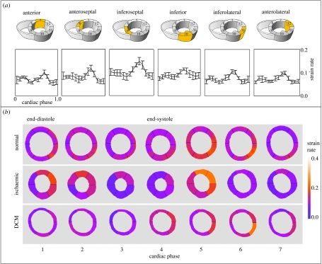
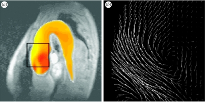
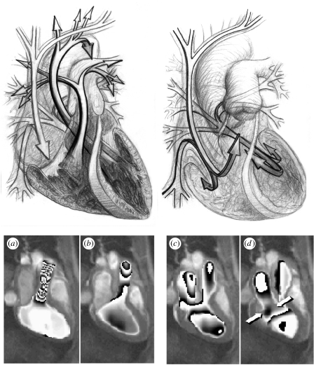
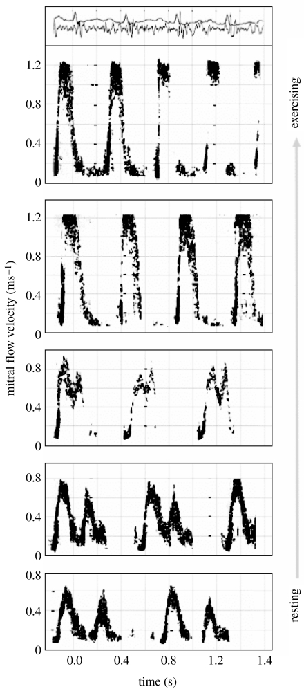
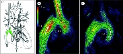
Heart failure due to coronary artery disease has considerable morbidity and poor prognosis. An understanding of the underlying mechanics governing myocardial contraction is a prerequisite for interpreting and predicting changes induced by heart disease. Gross changes in contractile behaviour of the myocardium are readily detected with existing techniques. For more subtle changes during early stages of cardiac dysfunction, however, a sensitive method for measuring, as well as a precise criterion for quantifying, normal and impaired myocardial function is required. The purpose of this paper is to outline the role of imaging, particularly cardiovascular magnetic resonance (CMR), for investigating the fundamental relationships between cardiac morphology, function and flow. CMR is emerging as an important clinical tool owing to its safety, versatility and the high-quality images it produces that allow accurate and reproducible quantification of cardiac structure and function. We demonstrate how morphological and functional assessment of the heart can be achieved by CMR and illustrate how blood flow imaging can be used to study flow and structure interaction, particularly for elucidating the underlying haemodynamic significance of directional changes and asymmetries of the cardiac looping. Future outlook on combining imaging with engineering approaches in subject-specific biomechanical simulation is also provided.


Figures

Figure 1
Figure 1
The principal blood flows within the heart are shown. The heart is divided into two sides that control the pulmonary (1–7) and the systemic circulations (8–13). Each side of the heart comprises an atrium that acts as a temporary reservoir, a ventricle that generates pulsatile flow, and a pair of valves that ensure flow remains unidirectional.
Figure 2
Figure 2
(a) Volume of the blood and myocardium of a normal LV over the cardiac cycle; (b) end-diastolic (7 ms) and (c) end-systolic (332 ms) CMR images of the four chambers of the heart; (d) ventricular contraction (7–332 ms) map that demonstrates the progressive displacements of the endocardial border through systole.
Figure 3
Figure 3
Maximum and minimum principal strain for 16 segments of the LV myocardium calculated using HARP imaging: (a) basal; (b) mid ventricular and (c) apical. Mean±s.d. values are shown for the five normal subjects and eight HCM patients.
Figure 4
Figure 4
Assessment of myocardial contractility with high sensitivity MR velocity imaging. (a) Anatomical structure of the image plane, (b) MR velocity measurement, (c) reconstructed longitudinal contractility mapping showing uniform contraction (sky blue) during systole and relaxation (red) during diastole for a normal subject and (d) contractility mapping for a patient with ischaemic heart disease, showing delayed contraction during systole and abnormal relaxation (broken and broadened red strip) during diastole.
Figure 5
Figure 5
(a) Mean±s.d. of the strain distribution over time for normal subjects in different regions of the heart and (b) normalized results in normal subjects over time for seven frames of the cardiac cycle. This can be compared to the strain rate distribution in an ischaemic and dilated cardiomyopathy patient. The strain rate images are aligned so that the anterior region is at the top of the image.
Figure 6
Figure 6
Pressure differences during flow into an aortic aneurysm: (a) calculated from the MR velocity measurements; (b) obtained by using the Navier–Stokes equations for incompressible fluids.
Figure 7
Figure 7
Drawings illustrate the principal directions of blood flow through the heart in systole and early diastole. Each of the main movements of blood involves acceleration followed by deceleration of flow. The pressure differences associated with the changes of momentum have been computed from magnetic resonance velocity maps of the left ventricular inflow and outflow tracts, viewed obliquely from below right. Differences of pressure are represented by shaded bands in the images below, 1 mm Hg per band. (a) Acceleration of flow into the outflow tract in early systole, with higher pressure in the ventricle than at aortic valve level, 184 ms; (b) subsequent deceleration, with reversal of the outflow pressure gradient, 408 ms; (c) acceleration from left atrium to LV at the beginning of diastole, with higher pressure in the atrium, 464 ms; (d) subsequent deceleration, with reversal of the inflow pressure gradient, 576 ms. The numbers represent the timing in milliseconds from the R wave of the ECG. The arrows indicate the positions of the mitral valve leaflets. On exercise, with greater velocities of flow and more rapid transition between systole and diastole, dynamic pressure differences will be much larger and of greater functional significance.
Figure 8
Figure 8
Pulsed Doppler ultrasound traces of mitral flow velocity (y-axis of each trace) against time (x-axis). Diastolic mitral inflow is biphasic at rest (lower trace) but monophasic on strenuous exercise (upper trace). At the very top are traces of the electrocardiogram and phonocardiogram corresponding to the exercising Doppler trace.
Figure 9
Figure 9
(a) Principal paths of flow through both sides of the human heart depicted as continuous bands, with the locations of the heart valves represented by rings. This shows the direction changes and asymmetries of the tortuous paths of flow. Flow in the right atrium viewed from the subject's right side. Magnetic resonance velocity data have been displayed as instantaneous streamlines. Flow from the SVC and IVC contribute to a forward rotating vortex in both (b) systolic and (c) diastolic phases, redirecting inflowing blood towards the region of the TV, which lies to the left of this plane, away from the viewer.

References

    1. Augst D, Barratt D, Hughes A, Glor F, Thom S, Xu X. Accuracy and reproducibility of CFD predicted wall shear stress using 3D ultrasound images. ASME J. Biomed. Eng. 2003;125:218–222. doi:10.1115/1.1553973 - DOI - PubMed
    1. Aurigemma G, Reichek N, Schiebler M, Axel L. Evaluation of mitral regurgitation by cine magnetic resonance imaging. Am. J. Cardiol. 1990;66:621–625. doi:10.1016/0002-9149(90)90491-I - DOI - PubMed
    1. Axel L, Dougherty L. MR imaging of motion with spatial modulation of magnetisation. Radiology. 1989;171:841–845. - PubMed
    1. Berne R.M. The heart. vol. 1. American Physiological Society; Bethesda, MD: 1979. Handbook of physiology: a critical, comprehensive presentation of physiological knowledge and concepts. Section 2: the cardiovascular system.
    1. Bogren H.G, Buonocore M.H. 4D magnetic resonance velocity mapping of blood flow patterns in the aorta in young vs elderly normal subjects. J. Magn. Reson. Imaging. 1999;10:861–869. doi:10.1002/(SICI)1522-2586(199911)10:5<861::AID-JMRI35>3.0.CO;2-E - DOI - PubMed