

Finite element analysis of a floating microstimulator
- PMID: 17601192
- PMCID: PMC3062506
- DOI: 10.1109/TNSRE.2007.897027
Finite element analysis of a floating microstimulator
Abstract
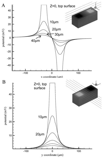
Analytical solutions for voltage fields in a volume conductor are available only for ideal electrodes with radially symmetric contacts and infinitely extending substrates. Practical electrodes for neural stimulation may have asymmetric contacts and finite substrate dimensions and hence deviate from the ideal geometries. For instance, it needs to be determined if the analytical solutions are adequate for simulations of narrow shank electrodes where the substrate width is comparable to the size of the contacts. As an extension to this problem, a "floating" stimulator can be envisioned where the substrate would be finite in all directions. The question then becomes how small this floating stimulator can be made before its stimulation strength is compromised by the decrease in the medium impedance between the contacts as the contacts are approaching each other. We used finite element modeling to solve the voltage and current profiles generated by these radially asymmetric electrode geometries in a volume conductor. The simulation results suggest that both the substrate size and the bipolar contact separation influence the voltage field when these parameters are as small as a few times the contact size. Both of these effects are larger for increasing elevations from the contact surface, and even stronger for floating electrodes (finite substrate in all directions) than the shank-type electrodes. Location of the contacts on the floating electrode also plays a role in determining the voltage field. The voltage field for any device size and current, and any specific resistance of the volume conductor can be predicted from these results so long as the aspect ratios are preserved.
Figures


Similar articles
-
Current density distributions, field distributions and impedance analysis of segmented deep brain stimulation electrodes.J Neural Eng. 2005 Dec;2(4):139-47. doi: 10.1088/1741-2560/2/4/010. Epub 2005 Nov 9. J Neural Eng. 2005. PMID: 16317238
-
Focalizing electrical neural stimulation with penetrating microelectrode arrays: a modeling study.J Neurosci Methods. 2012 Jul 30;209(1):250-4. doi: 10.1016/j.jneumeth.2012.05.006. Epub 2012 Jun 4. J Neurosci Methods. 2012. PMID: 22677176
-
Effect of planar microelectrode geometry on neuron stimulation: finite element modeling and experimental validation of the efficient electrode shape.J Neurosci Methods. 2015 Jun 15;248:51-8. doi: 10.1016/j.jneumeth.2015.03.024. Epub 2015 Apr 4. J Neurosci Methods. 2015. PMID: 25845480
-
A finite element method framework to model extracellular neural stimulation.J Neural Eng. 2022 Apr 7;19(2). doi: 10.1088/1741-2552/ac6060. J Neural Eng. 2022. PMID: 35320783 Review.
-
Selective electrical interfaces with the nervous system.Annu Rev Biomed Eng. 2002;4:407-52. doi: 10.1146/annurev.bioeng.4.020702.153427. Epub 2002 Mar 22. Annu Rev Biomed Eng. 2002. PMID: 12117764 Review.
Cited by
-
Chronic tissue response to untethered microelectrode implants in the rat brain and spinal cord.J Neural Eng. 2015 Feb;12(1):016019. doi: 10.1088/1741-2560/12/1/016019. Epub 2015 Jan 21. J Neural Eng. 2015. PMID: 25605679 Free PMC article.
-
Floating light-activated microelectrical stimulators tested in the rat spinal cord.J Neural Eng. 2011 Oct;8(5):056012. doi: 10.1088/1741-2560/8/5/056012. Epub 2011 Sep 14. J Neural Eng. 2011. PMID: 21914931 Free PMC article.
-
In vitro testing of floating light activated micro-electrical stimulators.Annu Int Conf IEEE Eng Med Biol Soc. 2009;2009:626-9. doi: 10.1109/IEMBS.2009.5334073. Annu Int Conf IEEE Eng Med Biol Soc. 2009. PMID: 19964480 Free PMC article.
-
Feasibility of Neural Stimulation With Floating-Light-Activated Microelectrical Stimulators.IEEE Trans Biomed Circuits Syst. 2011 Apr 5;2011(99):1. doi: 10.1109/TBCAS.2011.2114882. IEEE Trans Biomed Circuits Syst. 2011. PMID: 21552457 Free PMC article.
-
Remote Stimulation of Sciatic Nerve Using Cuff Electrodes and Implanted Diodes.Micromachines (Basel). 2018 Nov 14;9(11):595. doi: 10.3390/mi9110595. Micromachines (Basel). 2018. PMID: 30441831 Free PMC article.
References
-
- Schmidt EM, Bak MJ, Hambrecht FT, Kufta CV, O'Rourke DK, Vallabhanath P. Feasibility of a visual prosthesis for the blind based on intracortical microstimulation of the visual cortex. Brain. 1996 Apr.119(pt. 2):507–522. - PubMed
-
- Hillman T, Badi AN, Normann RA, Kertesz T, Shelton C. Cochlear nerve stimulation with a 3-dimensional penetrating electrode array. Otol. Neurotol. 2003 Sept.24(no. 5):764–768. - PubMed
-
- Otto KJ, Rousche PJ, Kipke DR. Microstimulation in auditory cortex provides a substrate for detailed behaviors. Hear Res. 2005 Dec.210(no. 1–2):112–7. - PubMed
-
- Anderson DJ, Najafi K, Tanghe SJ, Evans DA, Levy KL, Hetke JF, Hue XL, Zappia JJ, Wise KD. Batch fabricated thin-film electrodes for stimulation of the central auditory system. IEEE Trans. Biomed. Eng. 1989 Jul.36(no. 7):693–704. - PubMed
-
- Rousche PJ, Normann RA. Chronic intracortical microstimulation (ICMS) of cat sensory cortex using the Utah Intracortical Electrode Array. IEEE Trans. Rehabil. Eng. 1999 Mar.7(no. 1):56–68. - PubMed
Publication types
MeSH terms
Grants and funding
LinkOut - more resources
Full Text Sources
Other Literature Sources
Research Materials
