

Uniform deposition of protein incorporated mineral layer on three-dimensional porous polymer scaffolds
- PMID: 17618505
- PMCID: PMC2744812
- DOI: 10.1002/jbm.b.30877
Uniform deposition of protein incorporated mineral layer on three-dimensional porous polymer scaffolds
Abstract
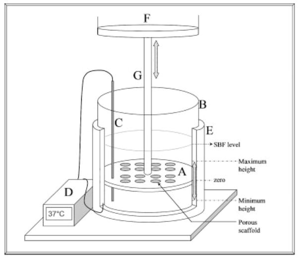
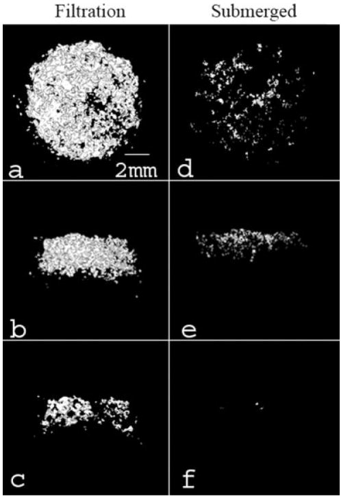
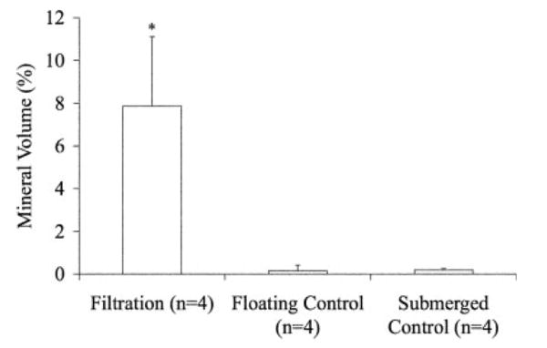
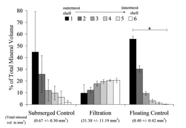
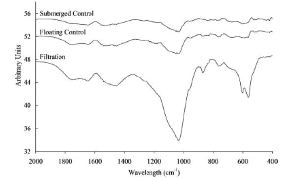
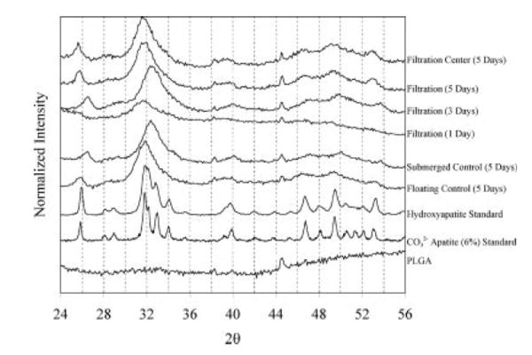
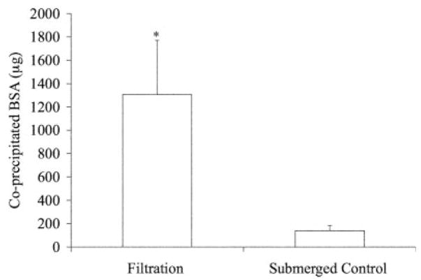
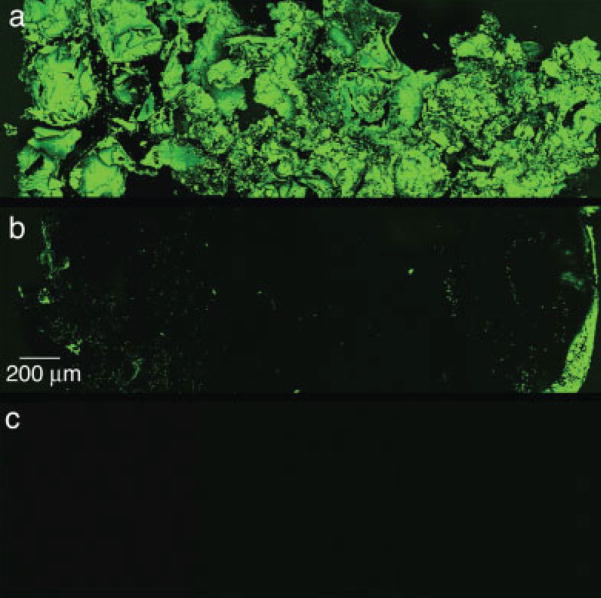
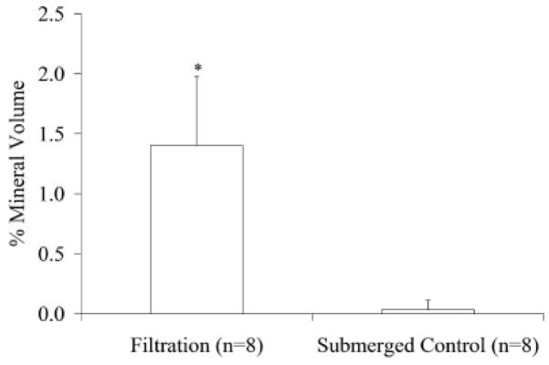
Inorganic-organic hybrid materials designed to facilitate bone tissue regeneration use a calcium phosphate mineral layer to encourage cell adhesion, proliferation, and osteogenic differentiation. Mineral formed on porous materials is often discontinuous through the thickness of the scaffold. This study aimed to uniformly coat the pores of three-dimensional (3D) porous, polymer scaffolds with a bone-like mineral layer in addition to uniformly incorporating a model protein within this mineral layer. A filtration system designed to induce simulated body fluid flow through the interstices of 3D polylactic-co-glycolic acid scaffolds (10-mm diameter x 2-mm thickness) illustrated that a uniform, continuous mineral layer can be precipitated on the pore surfaces of a 3D porous structure within 5 days. MicroCT analysis showed increased mineral volume percent (MV%) (7.86 +/- 3.25 MV%, p = 0.029) and continuous mineralization of filtered scaffolds compared with two static control groups (floating, 0.16 +/- 0.26 MV% and submerged, 0.20 +/- 0.01 MV%). Furthermore, the system was effective in coprecipitating a model protein, bone sialoprotein (BSA), within the mineral layer. A 10-fold increase in BSA incorporation was seen when coprecipitated filtered scaffolds (1308 +/- 464 microg) were compared to a submerged static control group (139 +/- 45 microg), p < 0.001. Confocal microscopy visually confirmed uniform coprecipitation of BSA throughout the thickness of the filtration scaffolds. The designed system enables 3D mineralization through the thickness of porous materials, and provides the option of including coprecipitated biomolecular cues within the mineral layer. This approach of providing a 3D conductive and osteoinductive environment could be conducive to bone tissue regeneration.
(c) 2007 Wiley Periodicals, Inc.
Figures
Similar articles
-
Spatial control of protein within biomimetically nucleated mineral.Biomaterials. 2006 Mar;27(7):1175-86. doi: 10.1016/j.biomaterials.2005.07.043. Epub 2005 Aug 31. Biomaterials. 2006. PMID: 16137760
-
Fabrication and characterization of poly(DL-lactic-co-glycolic acid)/zirconia-hybridized amorphous calcium phosphate composites.J Biomater Sci Polym Ed. 2006;17(4):403-18. doi: 10.1163/156856206776374124. J Biomater Sci Polym Ed. 2006. PMID: 16768292 Free PMC article.
-
Accelerated bonelike apatite growth on porous polymer/ceramic composite scaffolds in vitro.Tissue Eng. 2006 Oct;12(10):2997-3006. doi: 10.1089/ten.2006.12.2997. Tissue Eng. 2006. PMID: 17506618
-
Growth of continuous bonelike mineral within porous poly(lactide-co-glycolide) scaffolds in vitro.J Biomed Mater Res. 2000 Apr;50(1):50-8. doi: 10.1002/(sici)1097-4636(200004)50:1<50::aid-jbm8>3.0.co;2-f. J Biomed Mater Res. 2000. PMID: 10644963
-
Current understanding of osteoconduction in bone regeneration.Clin Orthop Relat Res. 1998 Oct;(355 Suppl):S267-73. doi: 10.1097/00003086-199810001-00027. Clin Orthop Relat Res. 1998. PMID: 9917646 Review.
Cited by
-
Physicochemical properties and applications of poly(lactic-co-glycolic acid) for use in bone regeneration.Tissue Eng Part B Rev. 2013 Aug;19(4):380-90. doi: 10.1089/ten.TEB.2012.0443. Epub 2013 Mar 1. Tissue Eng Part B Rev. 2013. PMID: 23350707 Free PMC article. Review.
-
Controlled nucleation of hydroxyapatite on alginate scaffolds for stem cell-based bone tissue engineering.J Biomed Mater Res A. 2010 Oct;95(1):222-34. doi: 10.1002/jbm.a.32833. J Biomed Mater Res A. 2010. PMID: 20574984 Free PMC article.
-
Cell and Material-Specific Phage Display Peptides Increase iPS-MSC Mediated Bone and Vasculature Formation In Vivo.Adv Healthc Mater. 2019 May;8(9):e1801356. doi: 10.1002/adhm.201801356. Epub 2019 Mar 5. Adv Healthc Mater. 2019. PMID: 30835955 Free PMC article.
-
Use of micro-computed tomography to nondestructively characterize biomineral coatings on solid freeform fabricated poly (L-lactic acid) and poly ((ε-caprolactone) scaffolds in vitro and in vivo.Tissue Eng Part C Methods. 2013 Jul;19(7):507-17. doi: 10.1089/ten.TEC.2012.0495. Epub 2013 Mar 11. Tissue Eng Part C Methods. 2013. PMID: 23134479 Free PMC article.
-
Using polymeric materials to control stem cell behavior for tissue regeneration.Birth Defects Res C Embryo Today. 2012 Mar;96(1):63-81. doi: 10.1002/bdrc.21003. Birth Defects Res C Embryo Today. 2012. PMID: 22457178 Free PMC article. Review.
References
-
- Wiesmann HP, Joos U, Meyer U. Biological and biophysical principles in extracorporal bone tissue engineering. Part II. Int J Oral Maxillofac Surg. 2004;33:523–530. - PubMed
-
- Parikh SN. Bone graft substitutes in modern orthopedics. Orthopedics. 2002;25:1301–1309. 1310–1311. - PubMed
-
- Muschler GF, Midura RJ. Connective tissue progenitors: practical concepts for clinical applications. Clin Orthop Relat Res. 2002;395:66–80. - PubMed
-
- Feinberg SE, Aghaloo TL, Cunningham LL., Jr Role of tissue engineering in oral and maxillofacial reconstruction: Findings of the 2005 AAOMS Research Summit. J Oral Maxillofac Surg. 2005;63:1418–1425. - PubMed
-
- Yaszemski MJ, Payne RG, Hayes WC, Langer R, Mikos AG. Evolution of bone transplantation: molecular, cellular and tissue strategies to engineer human bone. Biomaterials. 1996;17:175–185. - PubMed
Publication types
MeSH terms
Substances
Grants and funding
LinkOut - more resources
Full Text Sources
Other Literature Sources
Medical
