Cell force microscopy on elastic layers of finite thickness
- PMID: 17660320
- PMCID: PMC2025665
- DOI: 10.1529/biophysj.107.111328
Cell force microscopy on elastic layers of finite thickness
Abstract
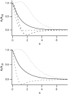
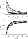
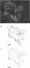
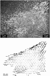
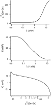
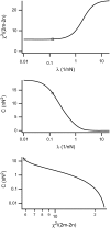
Forces applied by cells to substrates can be measured using soft substrates with embedded displacement markers. Traction forces are retrieved from microscopic images by determining the displacements of these markers and fitting the generating forces. Here we show that using elastic films of 5-10-microm thickness one can improve the spatial resolution of the technique. To this end we derived explicit equations for the mechanical response of an elastic layer of finite thickness to point forces. Moreover, these equations allow highly accurate force measurements on eukaryotic cells on films where finite thickness effects are relevant (below approximately 60 microm).
Figures



Similar articles
-
Elasticity of cardiac cells on the polymer substrates with different stiffness: an atomic force microscopy study.Phys Chem Chem Phys. 2011 Apr 28;13(16):7540-5. doi: 10.1039/c1cp20154a. Epub 2011 Mar 18. Phys Chem Chem Phys. 2011. PMID: 21416094
-
Determining substrate displacement and cell traction fields--a new approach.J Theor Biol. 2006 Oct 7;242(3):607-16. doi: 10.1016/j.jtbi.2006.05.005. Epub 2006 May 19. J Theor Biol. 2006. PMID: 16782134
-
Cellular traction force recovery: An optimal filtering approach in two-dimensional Fourier space.J Theor Biol. 2009 Aug 21;259(4):811-9. doi: 10.1016/j.jtbi.2009.05.005. Epub 2009 May 18. J Theor Biol. 2009. PMID: 19450610
-
Traction force microscopy on soft elastic substrates: A guide to recent computational advances.Biochim Biophys Acta. 2015 Nov;1853(11 Pt B):3095-104. doi: 10.1016/j.bbamcr.2015.05.028. Epub 2015 May 27. Biochim Biophys Acta. 2015. PMID: 26026889 Review.
-
Atomic force microscopy in mechanobiology: measuring microelastic heterogeneity of living cells.Methods Mol Biol. 2011;736:303-29. doi: 10.1007/978-1-61779-105-5_19. Methods Mol Biol. 2011. PMID: 21660735 Review.
Cited by
-
May the force be with your (immune) cells: an introduction to traction force microscopy in Immunology.Front Immunol. 2022 Jul 28;13:898558. doi: 10.3389/fimmu.2022.898558. eCollection 2022. Front Immunol. 2022. PMID: 35990636 Free PMC article. Review.
-
Dynamics of cellular focal adhesions on deformable substrates: consequences for cell force microscopy.Biophys J. 2008 Jul;95(2):527-39. doi: 10.1529/biophysj.107.127399. Epub 2008 Apr 11. Biophys J. 2008. PMID: 18408038 Free PMC article.
-
Micromechanical regulation in cardiac myocytes and fibroblasts: implications for tissue remodeling.Pflugers Arch. 2011 Jul;462(1):105-17. doi: 10.1007/s00424-011-0931-8. Epub 2011 Feb 11. Pflugers Arch. 2011. PMID: 21308471 Free PMC article. Review.
-
Three-dimensional traction force microscopy: a new tool for quantifying cell-matrix interactions.PLoS One. 2011 Mar 29;6(3):e17833. doi: 10.1371/journal.pone.0017833. PLoS One. 2011. PMID: 21468318 Free PMC article.
-
Elastomeric Pillar Cages Modulate Actomyosin Contractility of Epithelial Microtissues by Substrate Stiffness and Topography.Cells. 2023 Apr 26;12(9):1256. doi: 10.3390/cells12091256. Cells. 2023. PMID: 37174659 Free PMC article.
References
-
- Geiger, B., A. Bershadsky, R. Pankov, and K. Yamada. 2001. Transmembrane extracellular matrix—cytoskeleton crosstalk. Nat. Rev. Mol. Cell Biol. 2:793–805. - PubMed
-
- Linder, S., and M. Aepfelbacher. 2003. Podosomes: adhesion hot-spots of invasive cells. Trends Cell Biol. 13:376–385. - PubMed
-
- Litjens, S., J. de Pereda, and A. Sonnenberg. 2006. Current insights into the formation and breakdown of hemidesmosomes. Trends Cell Biol. 16:376–383. - PubMed
-
- Lo, S. 2006. Focal adhesions: what's new inside. Dev. Biol. 294:280–291. - PubMed
-
- Harris, A., P. Wild, and D. Stopak. 1980. Silicon rubber substrata: a new wrinkle in the study of cell locomotion. Science. 208:177–179. - PubMed
Publication types
MeSH terms
Substances
LinkOut - more resources
Full Text Sources

