Review
. 2006;1(1):3-14.
doi: 10.2147/nano.2006.1.1.3.

Micro- and nanotechnology in cell separation

Affiliations
Review

Micro- and nanotechnology in cell separation

Milica Radisic et al. Int J Nanomedicine. 2006.

Abstract

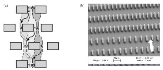
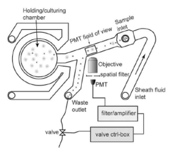
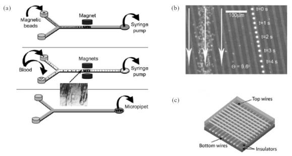
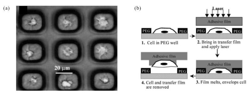
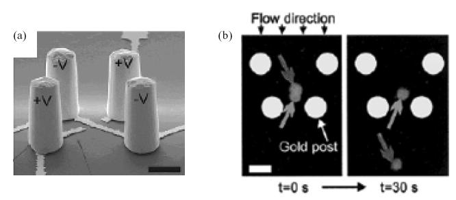
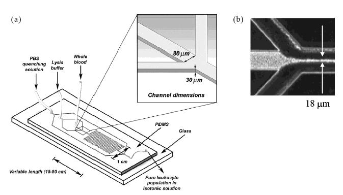
This review describes recent work in cell separation using micro- and nanoscale technologies. These devices offer several advantages over conventional, macroscale separation systems in terms of sample volumes, low cost, portability, and potential for integration with other analytical techniques. More importantly, and in the context of modern medicine, these technologies provide tools for point-of-care diagnostics, drug discovery, and chemical or biological agent detection. This review describes work in five broad categories of cell separation based on (1) size, (2) magnetic attraction, (3) fluorescence, (4) adhesion to surfaces, and (5) new emerging technologies. The examples in each category were selected to illustrate separation principles and technical solutions as well as challenges facing this rapidly emerging field.


Figures

Figure 1
Figure 1
Size-based separation. (a) A stream of fluid flowing at low Re (~10−3) is forced perpendicular to a series of obstacles of defined size and spacing (see arrows). The flow is confined to one of three fluid streamlines or “lanes” (denoted 1, 2, and 3). As shown above, if particles are smaller than the lane width, they continually zigzag between the obstacles, returning to their original lane assignment after traversing several rows of obstacles (zigzag mode). However, when the particles are larger than the lane width, they collide with the obstacles and displace only in one direction (displacement mode – not shown), allowing for separation to occur. Source: Huang LR, Cox EC, Austin RH, et al. 2004. Continuous particle separation through deterministic lateral displacement. Science, 304:987–90. Reproduced with permission. Copyright © 2004 AAAS. (b) A series of channels of successively smaller width is microfabricated thus creating a cell sieve. The flow is applied parallel to the channels as denoted by the solid arrow. Adapted from Mohamed H, McCurdy LD, Szarowski DH, et al. 2004. Development of a rare cell fractionation device: Application for cancer detection. IEEE Trans Nanobioscience, 3:251–6. Copyright © 2004 IEEE.
Figure 2
Figure 2
Microfluidic FACS system. Cells flow through a channel into an observation region. Upon detection of a target cell, a high-speed hydrodynamic valve switches fluid flow to send the cell into the holding/culturing chamber. Source: Wolff A, Perch-Nielsen IR, Larsen UD, et al. 2003. Integrating advanced functionality in a microfabricated high-throughput fluorescent-activated cell sorter. Lab Chip, 3:22–7. Reproduced with permission of The Royal Society of Chemistry. Abbreviations: PMT, photomultiplier tube; FACS, fluorescence-activated cell sorting.
Figure 3
Figure 3
Magnetic cell separation and sorting. (a) Y-shaped device used to separate immunogenic T cells from whole blood in three steps. Paramagnetic Protein A/anti-CD3-coated paramagnetic beads are flowed into the microdevice and immobilized using an external magnet. Subsequently, whole blood is introduced over the bed of magnetic beads, resulting in the capture of T cells. Upon removal of the external magnet, the T cells are flushed out of the microfluidic channel. Source: Furdui VI, Harrison DJ. 2004. Immunomagnetic T cell capture from blood for PCR analysis using microfluidic systems. Lab Chip, 4:614–8. Reproduced with permission of The Royal Society of Chemistry. (b) Combination of fluid flow (arrows) and ferromagnetic strips used to separate leukocytes on planar surfaces. Bright dots: time-lapse image of a tagged leukocyte moving along a ferromagnetic strip (left). Untagged red blood cells are moving along the direction of the fluid flow (right). Source: Inglis DW, Riehn R, Austin RH, et al. 2004. Continuous microfluidic immunomagnetic cell separation. Appl Phys Lett, 85:5093–5. Reproduced with permission. Copyright © 2004 American Institute of Physics. (c) Schematic diagram of a microelectromagnetic matrix for cell manipulation. The matrix consists of two wire meshes superimposed at 180°. Source: Lee H, Purdon AM, Westervelt RM. 2004. Manipulation of biological cells using a microelectromagnet matrix. Appl Phys Lett, 85:1063–5. Reproduced with permission. Copyright © 2004 American Institute of Physics.
Figure 4
Figure 4
(a) Poly(ethylene glycol) (PEG) microwells containing individual T and B lymphocytes. This type of capture allows subsequent extraction of individual cells by laser capture microdissection (shown schematically in (b)). Source: Revzin A, Sekine K, Sin A, et al. 2005. Development of a microfabricated cytometry platform for characterization and sorting of individual leukocytes. Lab Chip, 5:30–7. Reproduced with permission of The Royal Society of Chemistry.
Figure 5
Figure 5
Cell separation using dielectrophoretic traps. (a) A pseudo-colored SEM image showing a dioelectrophoresis (DEP) trap consisting of four trapezoidaly arranged gold electrodes. This configuration induces a dipole moment in the cell in the opposite direction to the electric field. The cell is repelled from the field and stably trapped at the quadrupole’s field minimum. (b) Two cells are loaded into the trap at low flow rate. The application of higher flow rate results in the ejection of one cell (dark grey arrow) from the trap leaving the other cell behind (grey arrow). Source: Voldman J, Gray ML, Toner M, et al. 2002. A microfabrication-based dynamic array cytometer. Anal Chem, 74:3984–90. Reproduced with permission. Copyright © 2002 American Chemical Society.
Figure 6
Figure 6
Microfluidic device for red blood cell lysis. (a) A stream of blood cells is induced to flow along the center of the main channel by two adjacent streams of lysis buffer. This narrowing, shown in (b), minimizes the need for lysis buffer diffusion and allows contact with the flowing blood at nearly the single cell level. Source: Sethu P, Anahtar M, Moldawer LL, et al. 2004. Continuous row microfluidic device for rapid erythrocyte lysis. Anal Chem, 76:6247–53. Reproduced with permission. Copyright © 2004 American Chemical Society. Abbreviations: PBS, phosphate buffered saline; PDMS, poly(dimethylsiloxane).

References

    1. Chang WC, Lee LP, Liepmann D. Biomimetic technique for adhesion-based collection and separation of cells in a microfluidic channel. Lab Chip. 2005;5:64–73. - PubMed
    1. Cho BS, Schuster TG, Zhu XY, et al. Passively driven integrated microfluidic system for separation of motile sperm. Anal Chem. 2003;75:1671–5. - PubMed
    1. Cobb JP, Mindrinos MN, Miller-Graziano C, et al. Application of genome-wide expression analysis to human health and disease. Proc Natl Acad Sci U S A. 2005;102:4801–6. - PMC - PubMed
    1. Deng T, Prentiss M, Whitesides GM. Fabrication of magnetic microfiltration systems using soft lithography. Appl Phys Lett. 2002;80:461–3.
    1. Feezor RJ, Baker HV, Mindrinos M, et al. Whole blood and leukocyte RNA isolation for gene expression analyses. Physiol Genomics. 2004;19:247–54. - PubMed

MeSH terms

LinkOut - more resources