

Custom-designed orthopedic implants evaluated using finite element analysis of patient-specific computed tomography data: femoral-component case study
- PMID: 17854508
- PMCID: PMC2100040
- DOI: 10.1186/1471-2474-8-91
Custom-designed orthopedic implants evaluated using finite element analysis of patient-specific computed tomography data: femoral-component case study
Abstract
Background: Conventional knee and hip implant systems have been in use for many years with good success. However, the custom design of implant components based on patient-specific anatomy has been attempted to overcome existing shortcomings of current designs. The longevity of cementless implant components is highly dependent on the initial fit between the bone surface and the implant. The bone-implant interface design has historically been limited by the surgical tools and cutting guides available; and the cost of fabricating custom-designed implant components has been prohibitive.
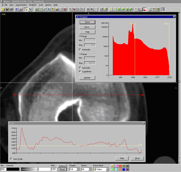
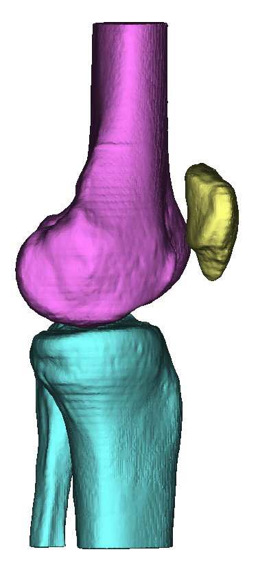
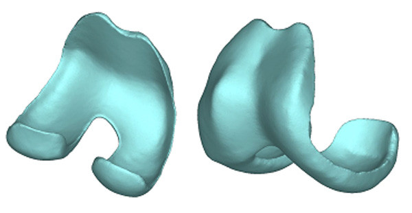
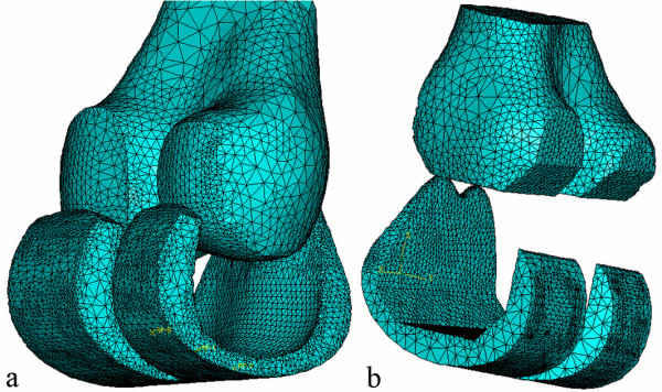
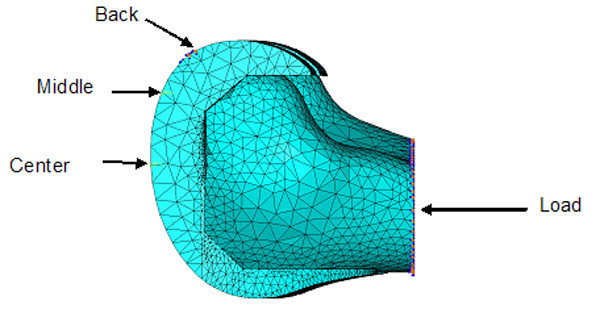
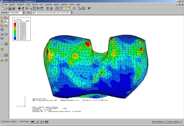
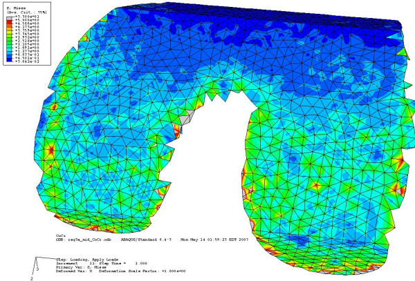
Methods: This paper describes an approach where the custom design is based on a Computed Tomography scan of the patient's joint. The proposed design will customize both the articulating surface and the bone-implant interface to address the most common problems found with conventional knee-implant components. Finite Element Analysis is used to evaluate and compare the proposed design of a custom femoral component with a conventional design.
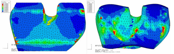
Results: The proposed design shows a more even stress distribution on the bone-implant interface surface, which will reduce the uneven bone remodeling that can lead to premature loosening.
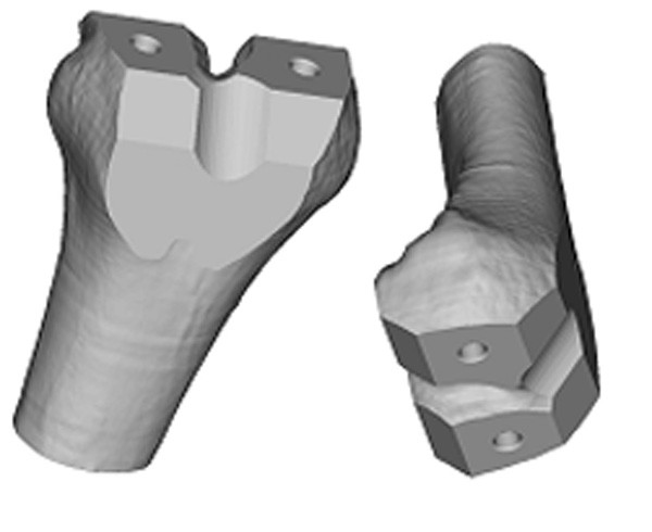
Conclusion: The proposed custom femoral component design has the following advantages compared with a conventional femoral component. (i) Since the articulating surface closely mimics the shape of the distal femur, there is no need for resurfacing of the patella or gait change. (ii) Owing to the resulting stress distribution, bone remodeling is even and the risk of premature loosening might be reduced. (iii) Because the bone-implant interface can accommodate anatomical abnormalities at the distal femur, the need for surgical interventions and fitting of filler components is reduced. (iv) Given that the bone-implant interface is customized, about 40% less bone must be removed. The primary disadvantages are the time and cost required for the design and the possible need for a surgical robot to perform the bone resection. Some of these disadvantages may be eliminated by the use of rapid prototyping technologies, especially the use of Electron Beam Melting technology for quick and economical fabrication of custom implant components.
Figures
References
-
- Sathasivam S, Walker PS, Pinder IM, Cannon SR, Briggs TWR. Custom constrained condylar total knees using CAD-CAM. Knee. 1999;6:49–53. doi: 10.1016/S0968-0160(98)00022-2. - DOI
-
- Taylor J, Rorabeck CH, Bourne RB, Inman K. Total knee arthroplasty in patients under the age of 50: long-term follow-up. Program and Abstracts of the 67th Annual Meeting of the American Academy of Orthopaedic Surgeons: 15–19 March 2000; Orlando, FL. 2000;Paper No. 185
-
- Krackow KA. The Technique of Total Knee Arthroplasty. St. Louis: The C. V. Mosby Company; 1990.
Publication types
MeSH terms
LinkOut - more resources
Full Text Sources
Other Literature Sources
Medical
