

Electric field perturbations of spiral waves attached to millimeter-size obstacles
- PMID: 17921205
- PMCID: PMC2212699
- DOI: 10.1529/biophysj.107.116244
Electric field perturbations of spiral waves attached to millimeter-size obstacles
Abstract
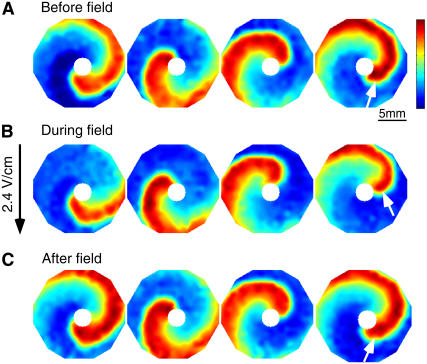
Reentrant spiral waves can become pinned to small anatomical obstacles in the heart and lead to monomorphic ventricular tachycardia that can degenerate into polymorphic tachycardia and ventricular fibrillation. Electric field-induced secondary source stimulation can excite directly at the obstacle, and may provide a means to terminate the pinned wave or inhibit the transition to more complex arrhythmia. We used confluent monolayers of neonatal rat ventricular myocytes to investigate the use of low intensity electric field stimulation to perturb the spiral wave. A hole 2-4 mm in diameter was created in the center to pin the spiral wave. Monolayers were stained with voltage-sensitive dye di-4-ANEPPS and mapped at 253 sites. Spiral waves were initiated that attached to the hole (n = 10 monolayers). Electric field pulses 1-s in duration were delivered with increasing strength (0.5-5 V/cm) until the wave terminated after detaching from the hole. At subdetachment intensities, cycle length increased with field strength, was sustained for the duration of the pulse, and returned to its original value after termination of the pulse. Mechanistically, conduction velocity near the wave tip decreased with field strength in the region of depolarization at the obstacle. In summary, electric fields cause strength-dependent slowing or detachment of pinned spiral waves. Our results suggest a means to decelerate tachycardia that may help to prevent wave degeneration.
Figures


Similar articles
-
Wave trains induced by circularly polarized electric fields in cardiac tissues.Sci Rep. 2015 Aug 25;5:13349. doi: 10.1038/srep13349. Sci Rep. 2015. PMID: 26302781 Free PMC article.
-
Spiral wave attachment to millimeter-sized obstacles.Circulation. 2006 Nov 14;114(20):2113-21. doi: 10.1161/CIRCULATIONAHA.105.598631. Epub 2006 Nov 6. Circulation. 2006. PMID: 17088465
-
Controlling activation site density by low-energy far-field stimulation in cardiac tissue.Phys Rev E Stat Nonlin Soft Matter Phys. 2012 Jun;85(6 Pt 1):061906. doi: 10.1103/PhysRevE.85.061906. Epub 2012 Jun 7. Phys Rev E Stat Nonlin Soft Matter Phys. 2012. PMID: 23005126
-
Imaging fibrillation/defibrillation in a dish.J Electrocardiol. 2007 Nov-Dec;40(6 Suppl):S62-5. doi: 10.1016/j.jelectrocard.2007.06.018. J Electrocardiol. 2007. PMID: 17993331 Free PMC article. Review.
-
Optical imaging of arrhythmias in tissue culture.J Electrocardiol. 2006 Oct;39(4 Suppl):S2-6. doi: 10.1016/j.jelectrocard.2006.04.010. J Electrocardiol. 2006. PMID: 17015066 Review.
Cited by
-
Removal of pinned scroll waves in cardiac tissues by electric fields in a generic model of three-dimensional excitable media.Sci Rep. 2016 Feb 24;6:21876. doi: 10.1038/srep21876. Sci Rep. 2016. PMID: 26905367 Free PMC article.
-
Wave trains induced by circularly polarized electric fields in cardiac tissues.Sci Rep. 2015 Aug 25;5:13349. doi: 10.1038/srep13349. Sci Rep. 2015. PMID: 26302781 Free PMC article.
-
Drift and termination of spiral waves in optogenetically modified cardiac tissue at sub-threshold illumination.Elife. 2021 Jan 27;10:e59954. doi: 10.7554/eLife.59954. Elife. 2021. PMID: 33502313 Free PMC article.
-
Optical imaging of voltage and calcium in cardiac cells & tissues.Circ Res. 2012 Feb 17;110(4):609-23. doi: 10.1161/CIRCRESAHA.111.247494. Circ Res. 2012. PMID: 22343556 Free PMC article. Review.
-
Mechanisms for the Termination of Atrial Fibrillation by Localized Ablation: Computational and Clinical Studies.Circ Arrhythm Electrophysiol. 2015 Dec;8(6):1325-33. doi: 10.1161/CIRCEP.115.002956. Epub 2015 Sep 10. Circ Arrhythm Electrophysiol. 2015. PMID: 26359479 Free PMC article.
References
-
- Qu, Z., J. N. Weiss, and A. Garfinkel. 2000. From local to global spatiotemporal chaos in a cardiac tissue model. Phys. Rev. E Stat. Phys. Plasmas Fluids Relat. Interdiscip. Topics. 61:727–732. - PubMed
-
- Panfilov, A. V. 1998. Spiral breakup as a model of ventricular fibrillation. Chaos. 8:57–64. - PubMed
-
- Gray, R., A. Pertsov, and J. Jalife. 1998. Spatial and temporal organization during cardiac fibrillation. Nature. 392:75–78. - PubMed
-
- Tung, L. 1996. Detrimental effects of electrical fields on cardiac muscle. IEEE Proc. 84:366–378.
Publication types
MeSH terms
Grants and funding
LinkOut - more resources
Full Text Sources
Other Literature Sources
Medical
