

Analytical and numerical quantification and comparison of the local electric field in the tissue for different electrode configurations
- PMID: 17937793
- PMCID: PMC2100058
- DOI: 10.1186/1475-925X-6-37
Analytical and numerical quantification and comparison of the local electric field in the tissue for different electrode configurations
Abstract
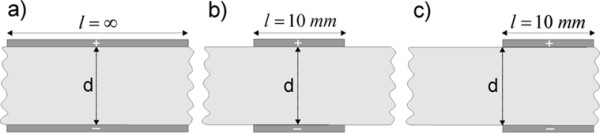
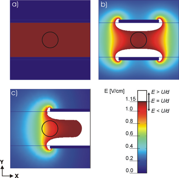
Background: Electrochemotherapy and gene electrotransfer are novel promising treatments employing locally applied high electric pulses to introduce chemotherapeutic drugs into tumor cells or genes into target cells based on the cell membrane electroporation. The main focus of this paper was to calculate analytically and numerically local electric field distribution inside the treated tissue in two dimensional (2D) models for different plate and needle electrode configurations and to compare the local electric field distribution to parameter U/d, which is widely used in electrochemotherapy and gene electrotransfer studies. We demonstrate the importance of evaluating the local electric field distribution in electrochemotherapy and gene electrotransfer.
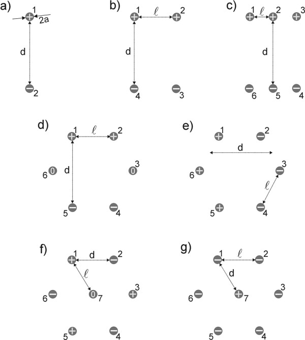
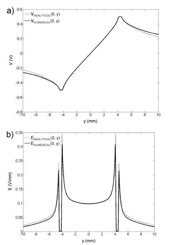
Methods: We analytically and numerically analyze electric field distribution based on 2D models for electrodes and electrode configurations which are most widely used in electrochemotherapy and gene electrotransfer. Analytical calculations were performed by solving the Laplace equation and numerical calculations by means of finite element method in two dimensions.
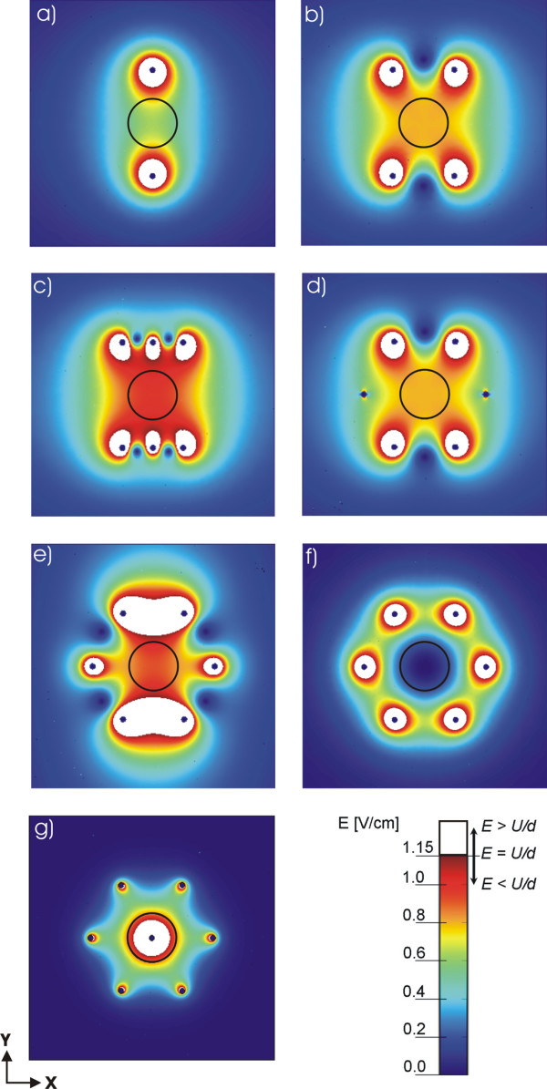
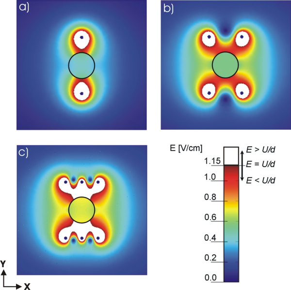
Results: We determine the minimal and maximal E inside the target tissue as well as the maximal E over the entire treated tissue for the given electrode configurations. By comparing the local electric field distribution calculated for different electrode configurations to the ratio U/d, we show that the parameter U/d can differ significantly from the actual calculated values of the local electric field inside the treated tissue. By calculating the needed voltage to obtain E > U/d inside the target tissue, we showed that better electric field distribution can be obtained by increasing the number and changing the arrangement of the electrodes.
Conclusion: Based on our analytical and numerical models of the local electric field distribution we show that the applied voltage, configuration of the electrodes and electrode position need to be chosen specifically for each individual case, and that numerical modeling can be used to optimize the appropriate electrode configuration and adequate voltage. Using numerical models we further calculate the needed voltage for a specific electrode configuration to achieve adequate E inside the target tissue while minimizing damages of the surrounding tissue. We present also analytical solutions, which provide a convenient, rapid, but approximate method for a pre-analysis of electric field distribution in treated tissue.
Figures
References
-
- Zimermann U. Electric field-mediated fusion and related electrical phenomena. Biochim Biophys Acta. 1982;694:227–277. - PubMed
-
- Neumann E, Sowers AE, Jordan CA. Electroporation and Electrofusion in Cell Biology. New York: Plenum Press; 1989.
-
- Weaver JC, Chizmadzhev YA. Theory of electroporation: A review. Bioelectrochem Bioenerg. 1996;41:135–60. doi: 10.1016/S0302-4598(96)05062-3. - DOI
Publication types
MeSH terms
LinkOut - more resources
Full Text Sources
Other Literature Sources
Medical
