Review
. 2007 Nov;37(3):246-57.
doi: 10.1007/s12033-007-0059-4. Epub 2007 Jul 12.

An overview of structural DNA nanotechnology

Affiliations
Review

An overview of structural DNA nanotechnology

Nadrian C Seeman. Mol Biotechnol. 2007 Nov.

Abstract

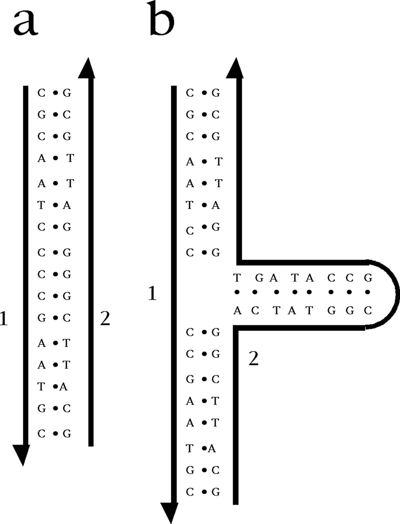
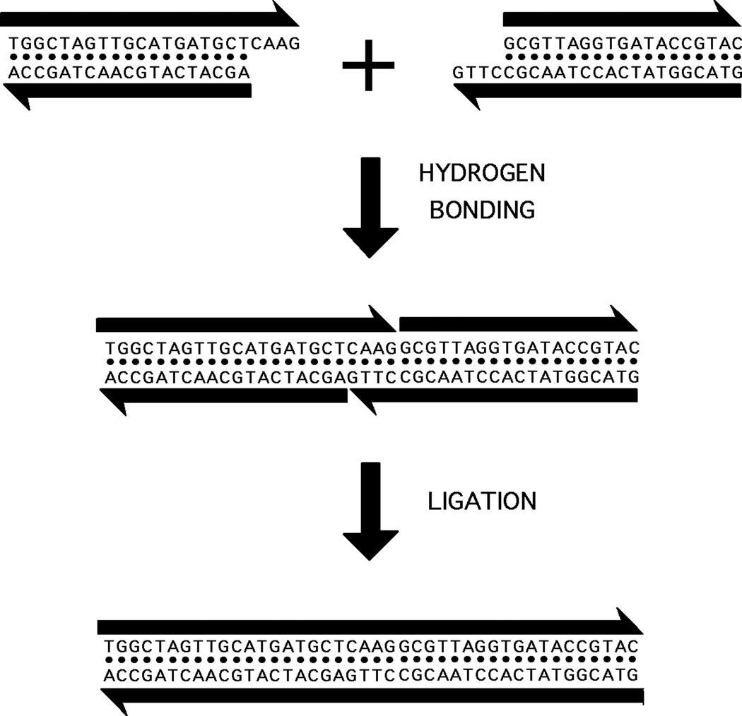
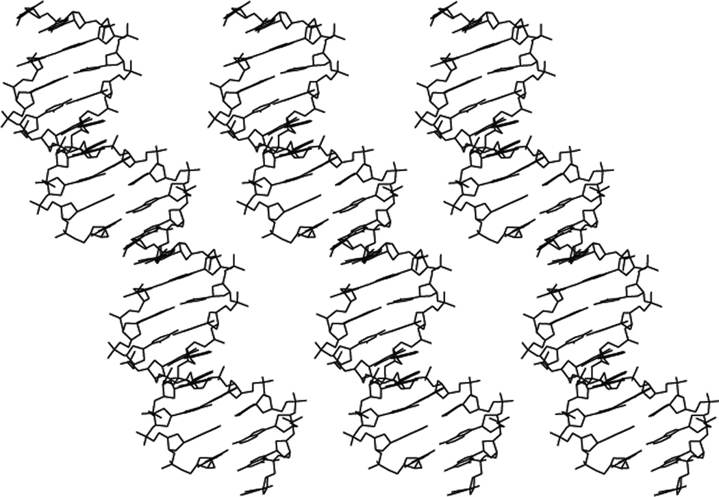
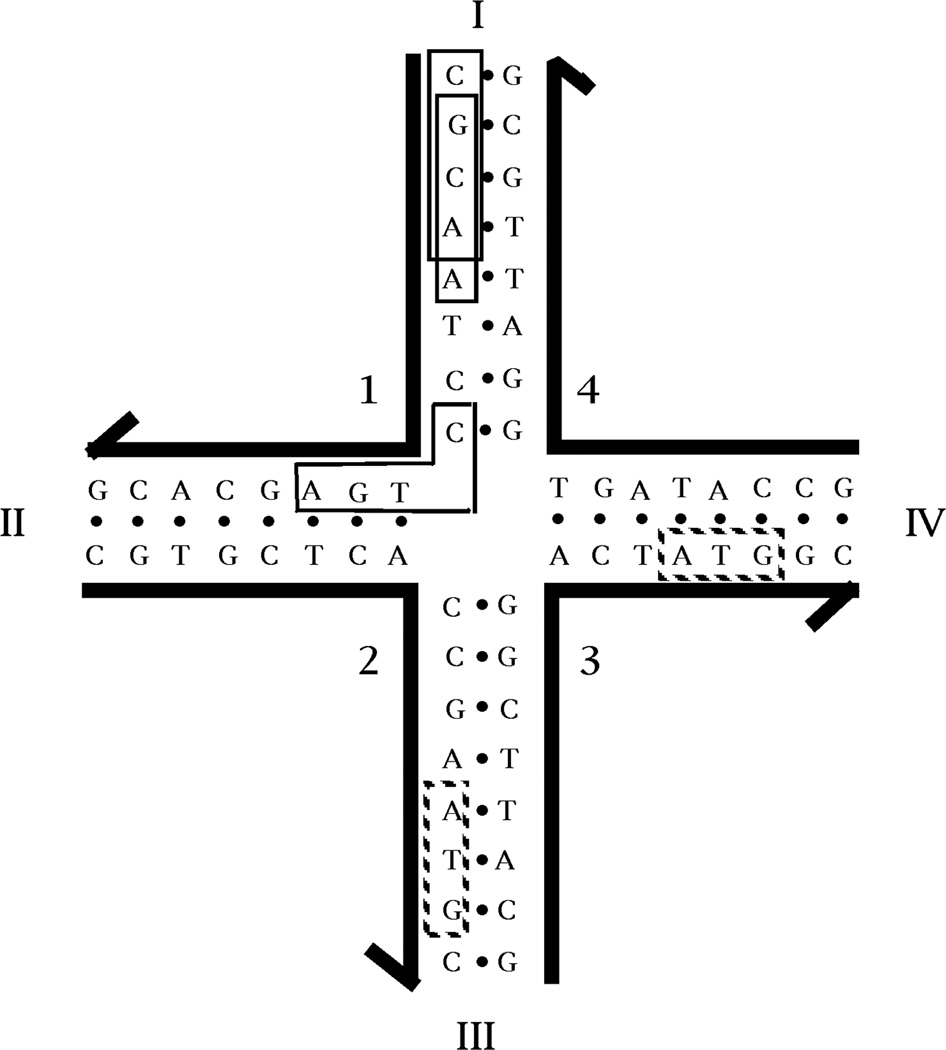
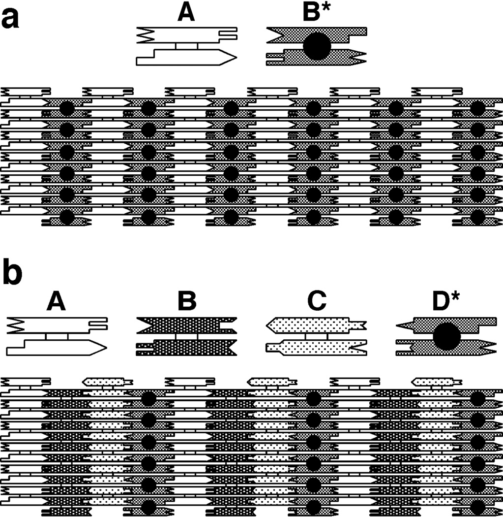
Structural DNA Nanotechnology uses unusual DNA motifs to build target shapes and arrangements. These unusual motifs are generated by reciprocal exchange of DNA backbones, leading to branched systems with many strands and multiple helical domains. The motifs may be combined by sticky ended cohesion, involving hydrogen bonding or covalent interactions. Other forms of cohesion involve edge-sharing or paranemic interactions of double helices. A large number of individual species have been developed by this approach, including polyhedral catenanes, a variety of single-stranded knots, and Borromean rings. In addition to these static species, DNA-based nanomechanical devices have been produced that are ultimately targeted to lead to nanorobotics. Many of the key goals of structural DNA nanotechnology entail the use of periodic arrays. A variety of 2D DNA arrays have been produced with tunable features, such as patterns and cavities. DNA molecules have be used successfully in DNA-based computation as molecular representations of Wang tiles, whose self-assembly can be programmed to perform a calculation. About 4 years ago, on the fiftieth anniversary of the double helix, the area appeared to be at the cusp of a truly exciting explosion of applications; this was a correct assessment, and much progress has been made in the intervening period.


Figures

Figure 1
Figure 1. Applications of DNA Periodic Arrays
(a) Biological Macromolecules Organized into a Crystalline Array. A cube-like box motif is shown, with sticky ends protruding from each vertex. Attached to the vertical edges are biological macromolecules that have been aligned to form a crystalline arrangement. The idea is that the boxes are to be organized into a host lattice by sticky ends, thereby arranging the macromolecular guests into a crystalline array, amenable to diffraction analysis. (b) Nanoelectronic Circuit Components Organized by DNA. Two DNA branched junctions are shown, with complementary sticky ends. Pendent from the DNA are molecules that can act like molecular wires. The architectural properties of the DNA are seen to organize the wire-like molecules, with the help of a cation, which forms a molecular synapse.
Figure 2
Figure 2. Inexact Complementarity in Branched DNA
On the left is a DNA duplex, labeled 'a'; its strands are numbered 1 and 2. On the right is a 3-arm branched junction, labeled 'b'. Its strands are also labeled 1 and 2, and strand 1 is identical to strand 1 of a. Every nucleotide of strand 1 in b is complemented by a nucleotide in strand 2 of b, but there are many nucleotides in the branch whose sequences are irrelevant to the complementarity between strands 2 and 1. The only well-defined complement to strand 1 is strand 2 of a.
Figure 3
Figure 3. Sticky Ended Cohesion
Two linear double helical molecules of DNA are shown at the top of the figure. The antiparallel backbones are indicated by the black lines terminating in half-arrows. The half-arrows indicate the 5'-->3' directions of the backbones. The right end of the left molecule and the left end of the right molecule have single-stranded extensions ('sticky ends') that are complementary to each other. The middle portion shows that, under the proper conditions, these bind to each other specifically by hydrogen bonding. The bottom panel shows that they can be ligated to covalency by the proper enzymes and cofactors.
Figure 4
Figure 4. The Crystal Structure of Infinite DNA Helices Held Together by Sticky Ends
Shown are three DNA double helices that consist of an infinite repeat of a decamer. The decamers are held together by complementary sticky ends, flanked by breaks in the DNA backbone. The key point is that the DNA around the sticky ends is the same as the rest of the DNA; it is all B-DNA, so the structure of any sticky-ended complex is known with high precision.
Figure 5
Figure 5. Motif Generation and Sample Motifs
(a) Reciprocal Exchange of DNA Backbones. Two strands are shown on the left, one filled, and one unfilled. Following reciprocal exchange, one strand is filled-unfilled, and the other strand is unfilled-filled. (b) Key Motifs in Structural DNA Nanotechnology. On the left is a Holliday junction (HJ), a 4-arm junction that results from a single reciprocal exchange between double helices. To its right is a double crossover (DX) molecule, resulting from a double exchange. To the right of the DX is a triple crossover (TX) molecule, that results from two successive double reciprocal exchanges. The HJ, the DX and the TX molecules all contain exchanges between strands of opposite polarity. To the right of the TX molecule is a paranemic crossover (PX) molecule, where two double helices exchange strands at every possible point where the helices come into proximity. To the right of the PX molecule is a JX2 molecule that lacks two of the crossovers of the PX molecule. The exchanges in the PX and JX2 molecule are between strands of the same polarity.
Figure 6
Figure 6. The Combination of Branched Motifs and Sticky Ends
At the left is a 4-arm branched junction with sticky ends, labeled X and its complement X', Y and its complement Y'. On the right four such molecules are combined to produce a quadrilateral. The sticky ends on the outside of the quadrilateral are available so that the structure can be extended to form a 2D lattice.
Figure 7
Figure 7. Sequence Symmetry Minimization Produces a Stable DNA Branched Junction
The junction shown is composed of four strands of DNA, labeled with Arabic numerals. The 3' end of each strand is indicated by the half-arrows. Each strand is paired with two other strands to form double helical arms; the arms are numbered with Roman numerals. The hydrogen bonded base paring that forms the double helices is indicated by the dots between the bases. The sequence of this junction has been optimized to minimize symmetry and non-Watson-Crick base pairing. Because there is no homologous twofold sequence symmetry flanking the central branch point, this junction cannot undergo the branch migration isomerization reaction. At the upper part of arm I, two of the 52 unique tetrameric elements in this complex are boxed; these are CGCA and GCAA. At the corner of strand 1, the sequence CTGA is boxed. This is one of twelve sequences in the complex (3 on each strand) that span a junction. The complements to each of these 12 sequences are not present. Whereas tetrameric elements have been used to assign the sequence of this molecule, there is redundancy in the molecule amongst trimers, such as the ATG sequences shown in dotted boxes.
Figure 8
Figure 8. Ligated products from flexible DNA components
(a) A Stick Cube and (b) a Stick Truncated Octahedron. The drawings show that each edge of the two figures contains two turns of double helical DNA. The twisting is confined to the central portion of each edge for clarity, but it actually extends from vertex to vertex. Both molecules are drawn as though they were constructed from 3-arm junctions, but the truncated octahedron has been constructed from 4-arm junctions, which has been omitted for clarity. (c-e) Deliberate Knots Constructed from DNA. The signs of the nodes are indicated. (c) A trefoil knot with negative nodes. (d) A figure-8 knot. (e) A trefoil knot with positive nodes. (f) Borromean Rings. Scission of any of the three rings shown results in the unlinking of the other two rings.
Figure 9
Figure 9. Tiling the Plane with DX Molecules
(a) A Two-Tile Pattern. The two helices of the DX molecule are represented schematically as rectangular shapes that terminate in a variety of shapes. The terminal shapes are a geometrical representation of sticky ends. The individual tiles are shown at the top of the drawing; the way tiles fit together using complementary sticky ends to tile the plane is shown at the bottom. The molecule labeled A is a conventional DX molecule, but the molecule labeled B* contains a short helical domain that protrudes from the plane of the helix axes; this protrusion is shown as a black dot. The black dots form a stripe-like feature in the array. The dimensions of the tiles are 4 nm × 16 nm in this projection. Thus, the stripe-like features should be about 32 nm apart. (b) A Four-Tile Pattern. The same conventions apply as in (a). The four tiles form an array in which the stripes should be separated by about 64 nm, as confirmed by AFM.
Figure 10
Figure 10. A Torsionally Driven DNA Device
On the left is a DNA circle that contains a fixed branch. There are four symmetric nucleotide pairs at the base of the branch, and these can undergo branch migration. With the normal twist of the DNA in the circle, the nucleotides are extruded from the circle. However, when the twist is decreased by the addition of ethidium, the nucleotides branch migrate to become part of the circle.
Figure 11
Figure 11. DNA-Based Nanomechanical Devices
(a) A Device Predicated on the B-Z Transition. The molecule consists of two DX molecules, connected by a segment containing proto-Z-DNA. The molecule consists of three cyclic strands, two on the ends drawn with a thin line, and one in the middle, drawn with a thick line. The molecule contains a pair of fluorescent dyes to report their separation by FRET. One is drawn as a filled circle, and the other as an empty circle. In the upper molecule, the proto-Z segment is in the B conformation, and the dyes are on the same side of the central double helix. In the lower molecule, the proto-Z segment is in the Z conformation, and the dyes are on opposite sides of the central double helix. The length of the proto-Z-DNA and its conformation are indicated at top and bottom by the two vertical lines flanking the conformation descriptor. (b) A Sequence-Dependent Device. This device uses two motifs, PX and JX2. The labels A, B, C and D on both show that there is a 180° difference between the wrappings of the two molecules. There are two strands drawn as thick lines at the center of the PX motif, and two strands drawn with thin lines at the center of the JX2 motif; in addition to the parts pairing to the larger motifs, each has an unpaired segment. These strands can be removed and inserted by the addition of their total complements (including the segments unpaired in the larger motifs) to the solution; these complements are shown in processes I and III as strands with black dots (representing biotins) on their ends. The biotins can be bound to magnetic streptavidin beads so that these species can be removed from solution. Starting with the PX, one can add the complement strands (process I), to produce an unstructured intermediate. Adding the set strands in process II leads to the JX2 structure. Removing them (III) and adding the PX set strands (IV) completes the machine cycle. Many different devices could be made by changing the sequences to which the set strands bind.
Figure 12
Figure 12. DNA-Based Computation
(a) Wang Tiles. On the left is a group of 16 Wang tiles. The edges of the tiles are flanked by a variety of patterns. These tiles assemble into the mosaic on the right according to the rule that each edge in the mosaic is flanked by the same pattern. The mosaic represents a calculation, adding 4 to 7 to obtain 11. The two addends are in the top row in the fourth and seventh column. The path through the calculation begins in the upper left corner, and continues on a diagonal until it encounters the vertical column in the fourth column. The path then switches to horizontal until the seventh column, and then again switches to the diagonal, terminating in the eleventh column. (After Grünbaum and Shephard, 1986). (b) The Relationship between Wang Tiles and Branched Junctions. The shadings are the same in both the tile and the sticky ends of the junction, indicating that the sticky ends on a branched junction can emulate a Wang tile. (c) The Components of a Cumulative XOR Calculation. TX tiles are shown as rectangles ending in sticky ends represented geometrically. The input x tiles are shown at the upper left; and the value of the tile is shown in the central domain. Initiator tiles C1 and C2 are shown in the upper right and the four possible y tiles are shown in the bottom row. The inputs of the y tiles is shown on their bottom domains. (d) The Self-Assembled Tiles. The strand structure of the TX tiles is illustrated on the upper left, with the reporter strand drawn with a thicker line. The assembly of tiles in a prototype calculation is shown, using the components illustrated in (c). The input 1, 1, 1, 0 produces an output of 1, 0, 1, 1 by successive binding of y tiles into the double sites created as the array assembles.

References

    1. Seeman NC. Structural DNA Nanotechnology: An Overview. In: Rosenthal Sandra J, Wright David W., editors. Methods in Molecular Biology 303: Bionanotechnology Protocols. Totowa, NJ: Humana Press; 2005. pp. 143–166. - PMC - PubMed
    1. Watson JD, Crick FHC. A structure for deoxyribose nucleic acid. Nature. 1953;171:737–738. - PubMed
    1. Seeman NC. Nucleic acid junctions and lattices. J. Theor. Biol. 1982;99:237–247. - PubMed
    1. Robinson BH, Seeman NC. The design of a biochip. Prot. Eng. 1987;1:295–300. - PubMed
    1. Winfree E. On the computational power of DNA annealing and ligation. In: Lipton EJ, Baum EB, editors. DNA Based Computing. 1996. pp. 199–219. Am. Math. Soc., Providence.

Publication types

LinkOut - more resources