. 2008;41(2):307-15.
doi: 10.1016/j.jbiomech.2007.09.016. Epub 2007 Oct 24.

Deformation of the human brain induced by mild angular head acceleration

Affiliations

Deformation of the human brain induced by mild angular head acceleration

Arash A Sabet et al. J Biomech. 2008.

Abstract

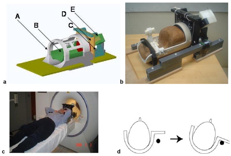
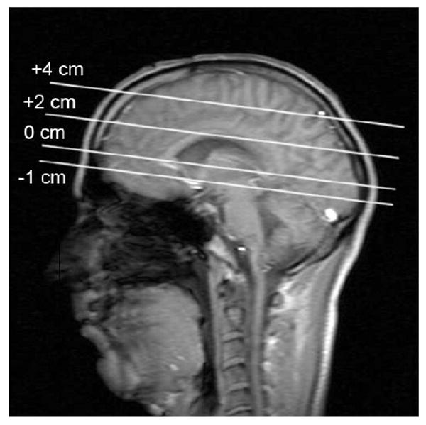
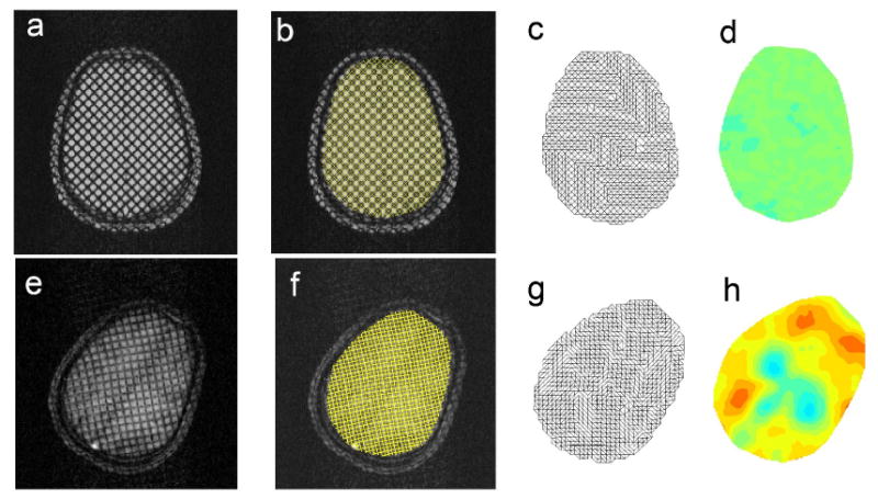
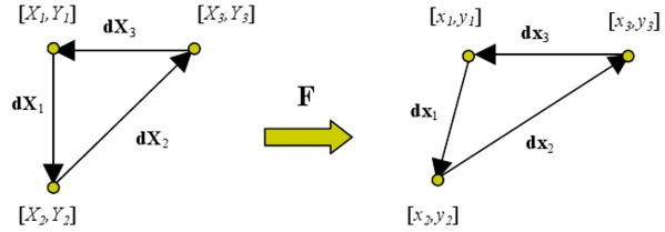
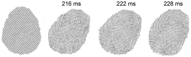
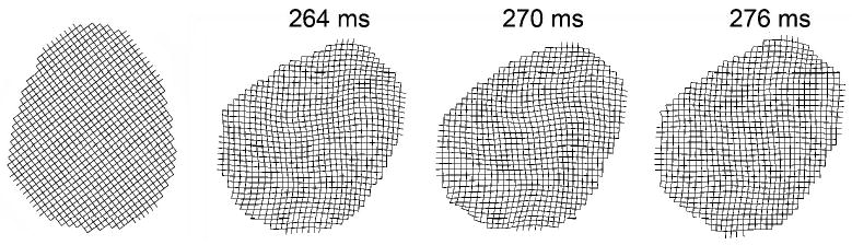
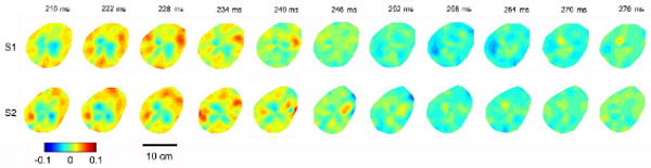
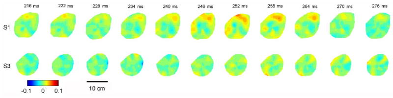
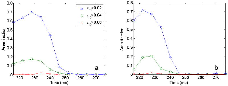
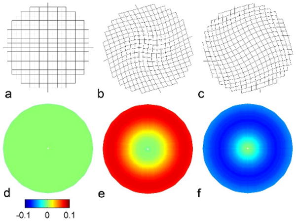
Deformation of the human brain was measured in tagged magnetic resonance images (MRI) obtained dynamically during angular acceleration of the head. This study was undertaken to provide quantitative experimental data to illuminate the mechanics of traumatic brain injury (TBI). Mild angular acceleration was imparted to the skull of a human volunteer inside an MR scanner, using a custom MR-compatible device to constrain motion. A grid of MR "tag" lines was applied to the MR images via spatial modulation of magnetization (SPAMM) in a fast gradient echo imaging sequence. Images of the moving brain were obtained dynamically by synchronizing the imaging process with the motion of the head. Deformation of the brain was characterized quantitatively via Lagrangian strain. Consistent patterns of radial-circumferential shear strain occur in the brain, similar to those observed in models of a viscoelastic gel cylinder subjected to angular acceleration. Strain fields in the brain, however, are clearly mediated by the effects of heterogeneity, divisions between regions of the brain (such as the central fissure and central sulcus) and the brain's tethering and suspension system, including the dura mater, falx cerebri, and tentorium membranes.


Figures

Figure 1
Figure 1
(a) Digital solid model of the device used to constrain head rotation in the MR scanner. (A) The MR head coil (antenna). (B) The rotating head cylinder. (C) The pin used to stop angular rotation. (D) Latch, which is released to initiate motion. (E) Plastic counterweight (600 grams). (b) Photograph of the physical device. (c) The head of the subject was secured inside the head rotator, and the entire assembly translated into the MRI coil for imaging. (d) Upon release of a latch, the head was rotated by the off-axis weight until it was abruptly stopped by a compliant pin. This soft stop provided approximately 250-300 rad/s2 angular deceleration.
Figure 2
Figure 2
Angular acceleration measurements recorded during repeated controlled head rotation (subject S2). Black bars indicate the volunteer-initiated latch release that initiated motion and triggered the scanning sequence; image data were acquired in the subsequent 540 ms.
Figure 3
Figure 3
Sagittal image illustrating the positions at which MR images were taken. The axial planes in which deformation data were collected are described with respect to a reference plane passing through the genu and splenium of the corpus callosum.
Figure 4
Figure 4
Illustration of strain estimation procedures. Reference image (top, a-d) and deformed images (bottom, e-h). (a, e) Tagged images. (b, f) HARP contours (synthetic tag lines). (c, g) triangular meshes generated from intersection points of HARP contours. (d, h) Radial-circumferential shear strain (ε) fields.
Figure 5
Figure 5
The deformation gradient tensor, F, maps each side of the reference triangle into a corresponding side of the deformed triangle (Eq. 1).
Figure 6
Figure 6
Grids of tag lines (HARP contours) showing “clockwise” shear deformation of the brain relative to the skull in subject S1. Displacements are scaled by a factor of five for visualization.
Figure 7
Figure 7
Grids of tag lines (HARP contours) showing “counterclockwise” shear deformation of the brain as it undergoes viscoelastic oscillation in subject S1. Displacements are scaled by a factor of five for visualization.
Figure 8
Figure 8
Radial-circumferential shear strain ε in subject S1 in four axial planes (-1 cm, 0 cm, +2 cm, +4 cm). Data are presented chronologically after initiation of the MR imaging sequence at the onset of head rotation (t=0 ms). Impact occurs at approximately t=200 ms.
Figure 9
Figure 9
Radial-circumferential shear strain ε in the axial plane +2 cm above the reference plane in two subjects (S1 and S2). Data are presented chronologically after initiation of the MR imaging sequence at the onset of head rotation (t=0ms).
Figure 10
Figure 10
Radial-circumferential shear strain ε in the axial reference plane (0 cm) in two subjects (S1 and S3). Data are presented chronologically after initiation of the MR imaging sequence at the onset of head rotation (t=0ms).
Figure 11
Figure 11
Radial-circumferential shear strain ε in the axial plane +4 cm above the reference plane in two subjects (S1 and S3). Data are presented chronologically after initiation of the MR imaging sequence at the onset of head rotation (t=0ms).
Figure 12
Figure 12
Fraction of image area in which radial-circumferential shear strain ε exceeds a specified threshold, ε. Data are from the strain fields shown in Figure 9 (axial plane +2 cm above the reference plane), plotted vs. time after impact. (a) Subject S1. (b) Subject S2.
Figure 13
Figure 13
Analytical predictions of shear deformation in a homogeneous, viscoelastic gel cylinder (instantaneous shear modulus G0 = 1710 Pa; long term shear modulus G =1334 Pa; time constant τ = 1.3 ms) contained in a rigid shell subjected to angular acceleration half-sine pulse of 40 ms duration and 250 rad/s2 amplitude. (a-c) Deformation of “tag” lines at t=0 and times of maximal and minimal shear deformation. (d-f) Corresponding radial-circumferential shear strains ε.

References

    1. Axel L, Dougherty L. MR imaging of motion with spatial modulation of magnetization. Radiology. 1989;171(3):841–845. - PubMed
    1. Bain AC, Meaney DF. Tissue-level thresholds for axonal damage in an experimental model of central nervous system white matter injury. Journal of Biomechanical Engineering. 2000;122:615–622. - PubMed
    1. Bayly PV, Cohen TS, Leister EP, Ajo D, Leuthardt EC, Genin GM. Deformation of the human brain induced by mild acceleration. Journal of Neurotrauma. 2005;22(8):845–56. - PMC - PubMed
    1. Bayly PV, Massouros PG, Sabet AA, Genin GM. Magnetic resonance rheometry of transient shear wave propagation in a viscoelastic gel cylinder. 2007 In review. - PMC - PubMed
    1. Gennarelli TA, Thibault LE, Tipperman R, Tomei G, Sergot R, Brown M, Maxwell WL, Graham DI, Adams JH, Irvine A, et al. Axonal injury in the optic nerve: a model simulating diffuse axonal injury in the brain. Journal of Neurosurgery. 1989;71(2):244–53. - PubMed

Publication types