. 2008 Feb 15;94(4):1252-66.
doi: 10.1529/biophysj.107.110171. Epub 2007 Nov 2.

Characterization of the resting MscS: modeling and analysis of the closed bacterial mechanosensitive channel of small conductance

Affiliations

Characterization of the resting MscS: modeling and analysis of the closed bacterial mechanosensitive channel of small conductance

Andriy Anishkin et al. Biophys J. .

Abstract

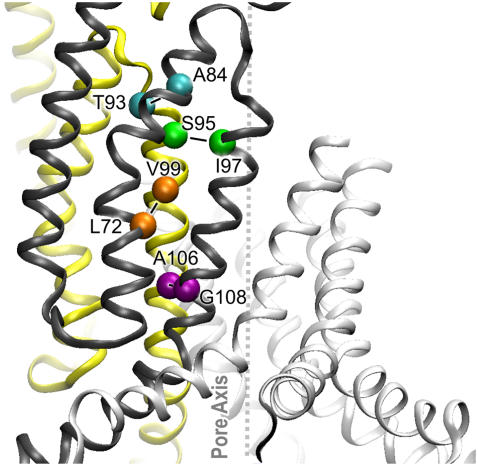
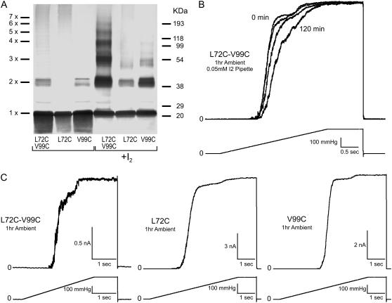
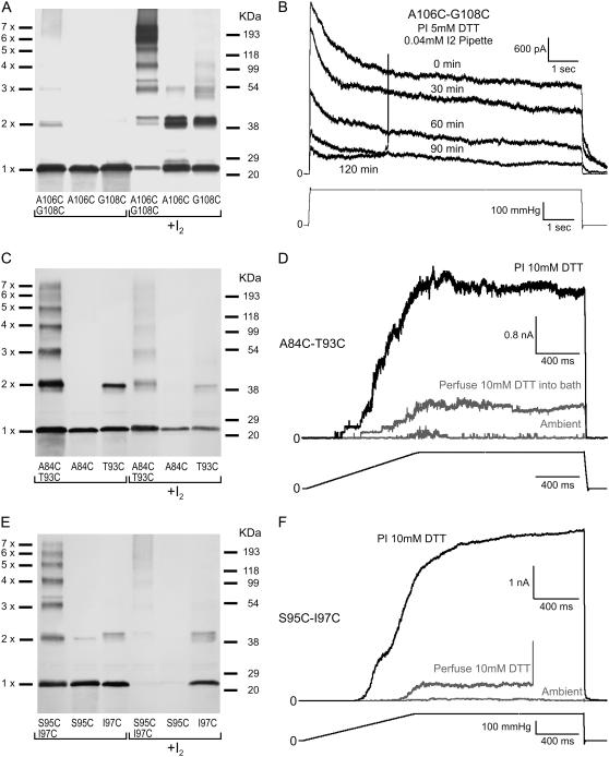
Channels from the MscS family are adaptive tension-activated osmolyte release valves that regulate turgor in prokaryotes and volume in plant chloroplasts. The crystal structure of Escherichia coli MscS has provided a starting point for detailed descriptions of its mechanism. However, solved in the absence of the lipid bilayer, this structure may deviate from a native conformation. In this study, we utilized molecular dynamics simulations and a new iterative extrapolated-motion protocol to pack the splayed peripheral TM1 and TM2 transmembrane helices along the central TM3 shaft. This modification restored the tension transmission route between the membrane and the channel gate. We also modeled the structure of the 26-amino acid N-terminal segments that were unresolved in the crystals. The resulting compact conformation, which we believe approximates the closed resting state of MscS, matches the hydrophobic thickness of the lipid bilayer with arginines 46, 54, and 74 facing the polar lipid headgroups. The pore-lining helices in this resting state feature alternative kinks near the conserved G121 instead of the G113 kinks observed in the crystal structure and the transmembrane barrel remains stable in extended molecular dynamics simulations. Further analysis of the dynamics of the pore constriction revealed several moderately asymmetric and largely dehydrated states. Biochemical and patch-clamp experiments with engineered double-cysteine mutants demonstrated cross-linking between predicted adjacent residue pairs, which formed either spontaneously or under moderate oxidation. The L72C-V99C bridge linking more peripheral TM2 to TM3 caused a shift of channel activation to higher pressures. TM3 to TM3 cross-links through the A84C-T93C, S95C-I97C, and A106C-G108C cysteine pairs were shown to lock MscS in a nonconductive state. Normal channel activity in these mutants could be recovered upon disulfide reduction with dithiothreitol. These results confirmed our modeling predictions of a closed MscS channel featuring a TM3 barrel that largely resembles the crystal conformation though with more tightly packed peripheral helices. From this closed-resting conformation, the TM3 helices must expand to allow for channel opening.


Figures

FIGURE 1
FIGURE 1
Generation of the complete resting conformation of MscS illustrated as step-by-step transformations of the crystal structure and modeling of the N-terminus. The complete crystal structure is presented as an inset next to panel A with the cytoplasmic cage domain shown in gray. Only the transmembrane pore region is shown in panels AF. The transformations in panels AE were performed on the entire protein, with the steering force applied to the transmembrane domain only. (A) The original crystal conformation of the transmembrane domain with splayed TM1 (orange) and TM2 (yellow) pairs of helices. The nearly parallel pore-lining TM3a segments (cyan) are followed by the C-terminal TM3b segments (blue) splayed after a sharp kink near glycine 113. (B) A compact conformation with restored contacts between the lipid-facing TM1-TM2 helices and the pore-lining TM3a helices. The peripheral TM1 helices are slightly bent and the TM1-TM2 loops are distorted due to clashes with splayed TM3b segments. (C) Expanded conformation featuring an open gate and straightened kinks between the TM3a and TM3b (blue) helices. The fragment above the channel (red) represents one of the most probable conformations of the N-terminal domain predicted using the Rosetta algorithm (see G). (D) The complete MscS model of the open state with attached N-terminal segments. Transitions from panels D to E and back represent compaction-expansion cycles performed using the extrapolated motion technique to test for the ability to undergo smooth and reversible transitions between the open and closed states. (F) The relaxed closed-state model representing the transmembrane domain with the adjacent part of the cytoplasmic cage after 8 ns of unrestrained all-atom simulation in the fully hydrated POPC bilayer, followed by symmetric annealing. In contrast to the crystal structure, the closed-state models (E and F) have a straightened kink near G 113, while an alternative kink forms around G121. (G) Ten most probable conformations of the N-terminus (40 residues) predicted by Rosetta. The first 26 residues in these ribbon representations are color-coded by residue name, whereas yellow regions correspond to the resolved helical stretches. The choice of the fragment and its final adjustment were done according to its ability to undergo unhindered transition between the states depicted in panels D and E.
FIGURE 2
FIGURE 2
All-atom MD simulation of the modeled resting state and the distribution of polar residues at the protein-lipid boundary. (A) Complete resting state model in the bilayer illustrated by a cross-sectional view captured in the middle of the unrestrained 8 ns simulation (sim2, see also Fig. 3). Shown as solvent-accessible surfaces, polar (green), basic (blue), and acidic (red) residues are exposed to the lipid headgroup regions, whereas nonpolar residues face hydrocarbon. Although the upper hydrophobic chamber is hydrated, neither water (cyan sticks), nor ions (Cl red or K+ blue, spheres) penetrate the dewetted hydrophobic constriction (yellow). (B) The same structure with the N-terminal domain (26 amino acids) removed. Nicks in the channel wall protrude down to the middle of the fatty acid chains and the absence of lipid-facing polar atoms suggests improper anchoring at the periplasmic rim of the channel. Y27 has spontaneously changed its position during the simulation from pore-facing as in the crystal structure, to one that is more peripheral and solvent-exposed. (C) Hydration energy profile for the lipid-exposed surface reveals a balanced distribution of polar groups in the complete resting state model (blue line) with a hydrophobic region near the midplane of the membrane (shown by horizontal dashed line) that is flanked by polar regions at ±16 Å representing the cytoplasmic and periplasmic rims. The model lacking the N-terminus (green line) shows a very small polar region at the periplasmic rim. Positioning the crystal structure (not shown) in the same way produces a maximum of polarity at −8 Å with a highly imbalanced overall distribution along the Z axis (red line). (D) The distribution of polar groups in a POPC bilayer simulated at an area of 64 Å2/lipid matches the distribution of the polar atoms in the closed MscS model. It is consistent with the notion that the route for the transmission of the lateral tension between lipid and protein lies at both the periplasmic and cytoplasmic rims of the channel. The lateral pressure/tension profile is shown in panel D with the red part of the curve representing the tension component. The distributions of lipid groups and pressure across the bilayer are taken from Gullingsrud and Schulten (46).
FIGURE 3
FIGURE 3
Geometrical parameters of the barrel and the degree of pore hydration in the course of a 15-ns MD simulation. (A) Effective radii of the periplasmic and cytoplasmic rims, outer chamber and of the constriction over the stages of simulation with the restricted backbone (rsbb), first unrestrained simulation (sim1), symmetry-driven annealing (symm1), the second unrestrained simulation (sim2), and the second symmetric annealing (symm2) (estimated every 50 ps). (B) Distances from the pore axis to the closest and the most distant α-carbons of equivalent residues in the heptamer that illustrate the ellipticity of the outer chamber (A98 and A102) and constriction (L105 and L109), estimated every 10 ps. (C) Conformational exchange in the pore illustrated by the radial motion of subunits. Positions of the α-carbons of A102 residues in individual subunits (numbered 1–7) were tracked every 10 ps. Residues closest to the pore axis at a given moment are marked by a magenta dot, whereas those most deviating from the axis are designated by a blue dot. Plots for the residues A98, L105, and L109 (not presented) illustrated the ellipticity of the barrel in the same way as this one for A102. (D) Z-coordinates of water molecules illustrating the degree of hydration of the pore constriction and vestibules scored every 1 ps.
FIGURE 4
FIGURE 4
Superimposed representations of the pore-forming helices shown by thin ribbons passing through the α-carbons. Only two opposing helices are shown to illustrate the width of the barrel. TM3 helices in the initial crystal conformation (PDB ID 1MXM) (red), the symmetrized final conformation after an 8 ns simulation (blue), and the most compact state of the TM3 barrel optimized through Monte Carlo simulations (green; depicted from the coordinates kindly provided by J. Bowie) (24). Residues L105 and L109 are shown in stick representation. Note that besides slightly tighter packing of TM3 helices, the major deviation of the modeled resting conformation (blue) from the crystal structure (red) is in the lowered position of the TM3b segment due to the alternative kink at G121 as opposed to G113 in the crystals.
FIGURE 5
FIGURE 5
Intersubunit contacts in the compact bilayer-equilibrated model of the MscS transmembrane domain in the closed state. Two adjacent subunits are shown in ribbon representation (yellow and black). TM1, TM2, and TM3 helices are in order from left to right. The α-carbons of critical residues are shown as spheres.
FIGURE 6
FIGURE 6
Effects of disulfide cross-link formation in L72C-V99C. Multimerization patterns and functional behavior of mutant channels in patch-clamp. This pair is predicted to link TM2 to TM3 of adjacent subunits. (A) Western blot indicating cross-linking products in the double cysteine mutant separated alongside the products generated in single cysteine controls L72C and V99C under ambient conditions (unmarked) or by adding 0.03 mM iodine (marked +I2). (B) The effect of adding iodine (0.05 mM) from the patch pipette (periplasm) on the activity of the L72C-V99C mutant. Spheroplasts were preincubated under ambient conditions for 1 h. The data show a strong rightward shift of the activation curves upon exposure to I2 signifying channel modification by disulfide formation. Current traces were normalized to the maximal observed current to emphasize the pressure shift (see text for details). (C) Activation of the double cysteine mutant and the single cysteine controls (L72C and V99C) by saturating pressure ramps under ambient conditions. Double mutant activation is heterogeneous, displaying at least two populations of channels. Activities of the controls are like WT in agreement with low disulfide formation under ambient conditions shown in Western analysis.
FIGURE 7
FIGURE 7
Disulfide cross links between adjacent TM3 helices and their inhibitory effects on channel gating. (A) Cross-linking patterns of A106C-G108C located in the gate region of the pore and corresponding single cysteine mutants. (B) Patch-clamp traces displaying a reduction of the A106C-G108C population current with gradual oxidation as 0.04 mM I2 reaches the patch through a sucrose plug. (C) Cross-linking patterns of the A84C-T93C and (E) S95C-I97C mutants with their single cysteine controls. These pairs are located in the upper part of the transmembrane barrel and form disulfides spontaneously under ambient conditions. (D and F) Corresponding sets of patch-clamp traces show that under ambient conditions these mutant channels exhibit very low activity (shaded traces). Perfusion of 10 mM DTT into the bath restores a small fraction of activity (shaded), whereas preincubation of spheroplasts with 10 mM DTT for 1 h restores the population current (solid).

Similar articles

Cited by

References

    1. Levina, N., S. Totemeyer, N. R. Stokes, P. Louis, M. A. Jones, and I. R. Booth. 1999. Protection of Escherichia coli cells against extreme turgor by activation of MscS and MscL mechanosensitive channels: identification of genes required for MscS activity. EMBO J. 18:1730–1737. - PMC - PubMed
    1. Pivetti, C. D., M. R. Yen, S. Miller, W. Busch, Y. H. Tseng, I. R. Booth, and M. H. Saier, Jr. 2003. Two families of mechanosensitive channel proteins. Microbiol. Mol. Biol. Rev. 67:66–85 (table of contents.). - PMC - PubMed
    1. Haswell, E. S., and E. M. Meyerowitz. 2006. MscS-like proteins control plastid size and shape in Arabidopsis thaliana. Curr. Biol. 16:1–11. - PubMed
    1. Nakayama, Y., K. Fujiu, M. Sokabe, and K. Yoshimura. 2007. Molecular and electrophysiological characterization of a mechanosensitive channel expressed in the chloroplasts of Chlamydomonas. Proc. Natl. Acad. Sci. USA. 104:5883–5888. - PMC - PubMed
    1. Okada, K., P. C. Moe, and P. Blount. 2002. Functional design of bacterial mechanosensitive channels. Comparisons and contrasts illuminated by random mutagenesis. J. Biol. Chem. 277:27682–27688. - PubMed

Publication types

LinkOut - more resources