. 2007 Nov;5(11):e318.
doi: 10.1371/journal.pbio.0050318.

Draft crystal structure of the vault shell at 9-A resolution

Affiliations

Draft crystal structure of the vault shell at 9-A resolution

Daniel H Anderson et al. PLoS Biol. 2007 Nov.

Abstract

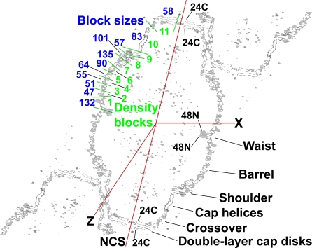
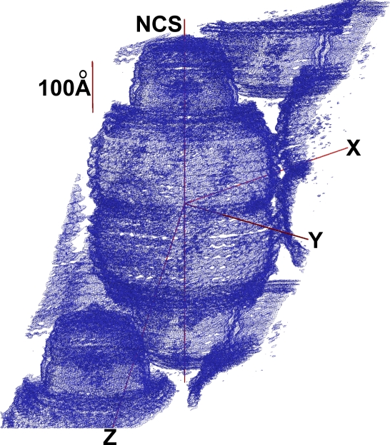
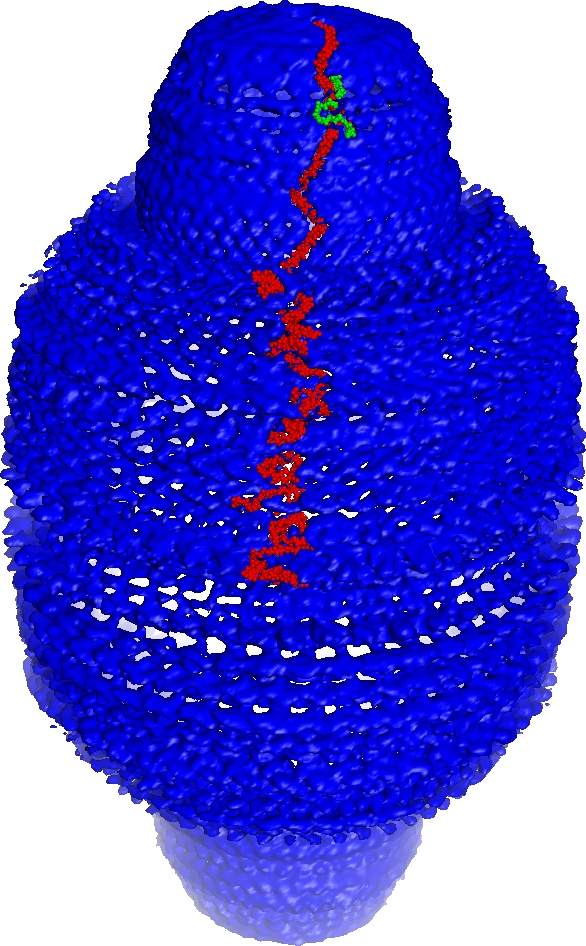
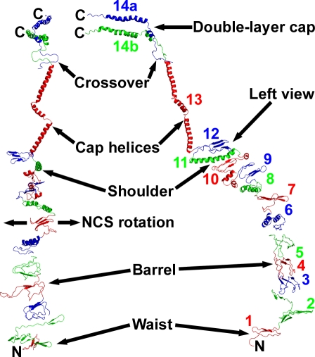
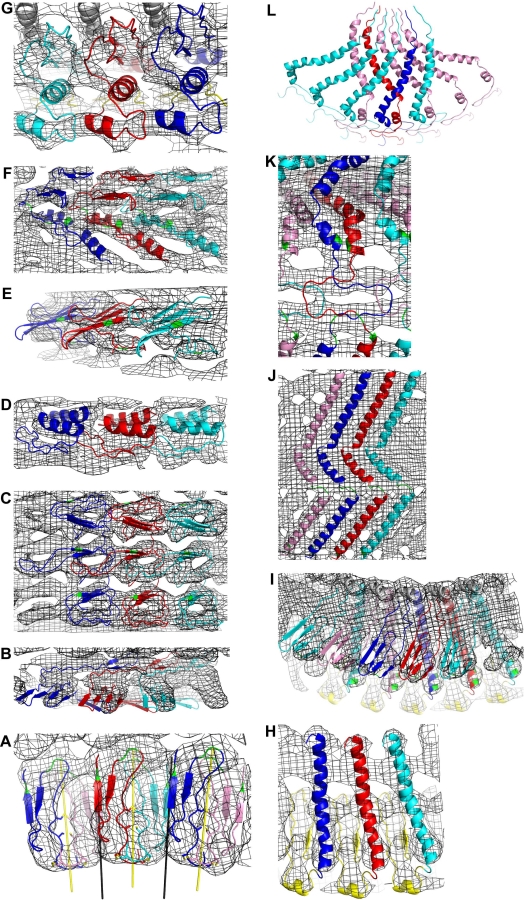
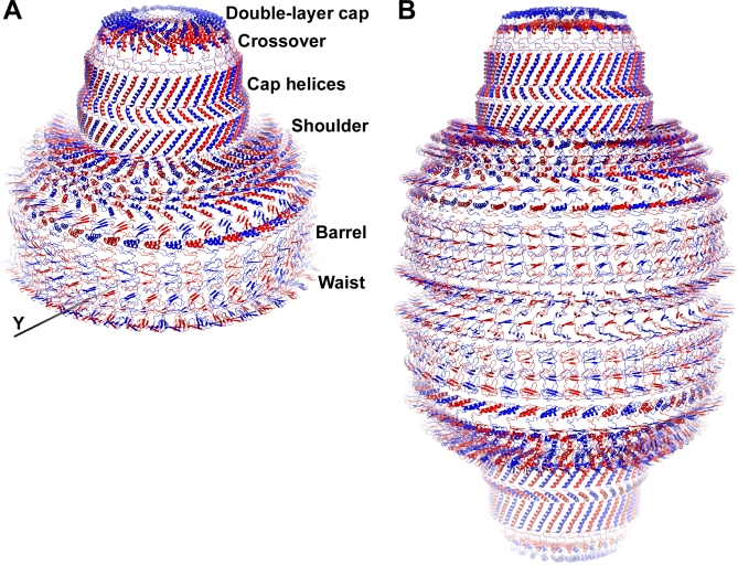
Vaults are the largest known cytoplasmic ribonucleoprotein structures and may function in innate immunity. The vault shell self-assembles from 96 copies of major vault protein and encapsulates two other proteins and a small RNA. We crystallized rat liver vaults and several recombinant vaults, all among the largest non-icosahedral particles to have been crystallized. The best crystals thus far were formed from empty vaults built from a cysteine-tag construct of major vault protein (termed cpMVP vaults), diffracting to about 9-A resolution. The asymmetric unit contains a half vault of molecular mass 4.65 MDa. X-ray phasing was initiated by molecular replacement, using density from cryo-electron microscopy (cryo-EM). Phases were improved by density modification, including concentric 24- and 48-fold rotational symmetry averaging. From this, the continuous cryo-EM electron density separated into domain-like blocks. A draft atomic model of cpMVP was fit to this improved density from 15 domain models. Three domains were adapted from a nuclear magnetic resonance substructure. Nine domain models originated in ab initio tertiary structure prediction. Three C-terminal domains were built by fitting poly-alanine to the electron density. Locations of loops in this model provide sites to test vault functions and to exploit vaults as nanocapsules.


Conflict of interest statement

Competing interests. The authors have declared that no competing interests exist.

Figures

Figure 1
Figure 1. Thin Section of Crystalline Vault Electron Density
The red lines show the crystal x and z directions, and the direction of the high-symmetry vault axis (marked NCS for noncrystallographic symmetry). The two neighboring vaults at upper right and lower left are related to the central vault by translations along the crystal z direction. The vault and the map are centered at (0,0,0) (contoured box is 530 Å along the crystal x-axis, 5-Å thick on y, and 845 Å along z). Regions of the vault discussed in the text are labeled at lower right. The vault model is 675 Å tip-to-tip and 417 Å in diameter at the widest part of the barrel. The 96 N termini are inside the vault at the waist region (marked 48N). Pairs of MVP chains become nonequivalent in the crossover zone as they approach the double-layer, C-terminal disk regions (C termini of the model are marked 24C). The vault model leaves ∼29-Å holes between C termini. The green lines at upper left mark the partitions between density blocks 1–11 used for “dot model refinement.” These partitions were chosen for convenience of handling files and do not match the cpMVP model domains (Table 1 and Figure 4). The blue numbers at upper left are density block size estimates: (873 residues) × (dots in block)/(total dots). The block size estimates were used for initial placement of cpMVP model domain 7. This figure, including the red and green lines, was made with XFIT of XtalView [40] and RENDER of Raster3D [44], and was labeled with Adobe Photoshop.
Figure 2
Figure 2. Overall View of the cpMVP Vault Averaged Electron Density Map, at about 9-Å Resolution, in the Context of the Crystal Packing
This electron density map (wire frame representation) resulted from applying solvent flattening and a 48-fold rotational symmetry averaging to the featureless cryo-EM electron density. Separation into globules of density showed that the MVP chain folds into a series of domains. The short red line is a 100-Å scale bar. The line marked NCS shows the noncrystallographic symmetry axis used for phasing. One of the 48 2-fold axes through the vault waist is coincident with the crystal 2-fold in the y direction (perpendicular to NCS axis). The figure was made using XFIT of XtalView and RENDER of Raster3D, then labeled with Adobe Photoshop. A section through the top of this figure is part of Figure S1.
Figure 3
Figure 3. Overall View of Dot-Refined Vault Electron Density with the Unique Parts of the cpMVP Model Inserted
One copy of the cpMVP model is shown as red atoms, from its N terminus at the waist to the crossover zone near the top (as in Figure 4). Two nonequivalent copies of cpMVP model are shown from the crossover to the C termini (the path of the green cpMVP model is mostly occluded; see Figure 1 for orientation). The electron density map coefficients were F observed, and the phase set was the enantiomer of the phases from the slow-averaged Dot Model 6. The contour level was 1.2σ. The electron density becomes less symmetric near crystal lattice contacts (left of center, foreground). The map and masks were produced with CCP4 programs [31]. Surrounding electron density was masked off to make this figure. The density around the cpMVP model was deleted with an inverse mask (inversion performed with MAMA [45]). The opaque iso-surface representation with “fog” representing distance was drawn with PyMOL [46].
Figure 4
Figure 4. The Unique Parts of the cpMVP Model, in Two Overall Views
The current cpMVP model contains 749 of the expected 873 cpMVP residues. The model is represented by ribbons. In the right part of the figure, the cpMVP model is oriented to resemble the cross-section shapes in Figures 1, S4, S5, and S6. The arrow at far right shows the approximate view direction for the left part of the figure. In the left view of the model, the symmetry-averaging direction is left-right (NCS axis is vertical, behind the page; direction of rotation around the NCS axis is marked NCS). Domain colors alternate (red-green-blue), with color transitions at residue numbers listed in Table 1. The colored domain numbers in the right part of the figure mark the domains and also show approximate viewpoints for Figure 5 (except domain 11). Both views of the model show one cpMVP chain (chain B) from the N-terminal residue Gly 3T to residue 715 just under the crossover zone of domains 14a and 14b. At the crossover (Figure 5k), the 48-fold symmetry transitions to 24-fold. Two cpMVP chains (chains A and B) are shown on their nonequivalent paths from the crossover to the C termini of domains 14a and 14b (two residue 779′s marked C). The cpMVP dimer model (PDB entry 2QZV) was completed from the unique model shown here by rotation of chain B residues 3T to 715 by one leftward increment of 48-fold NCS rotation. The cpMVP dimer model is 354 Å and 368 Å from the N termini to their corresponding inner and outer C termini. The residue numbers and locations in this model will help identify trial modification sites for engineered vaults. The two figure components were made with PyMOL [46], then combined and labeled with Adobe Photoshop.
Figure 5
Figure 5. CpMVP Domain Models
The cpMVP chains are shown in ribbon representation. Except as noted, chain A (leading to outer C terminus) is blue. NCS-related type A chains are cyan. Chain B (leading to inner C terminus) is red. NCS-related type B chains are pink. Residues discussed in the text are green. The F observed electron density map is displayed as wire frame on a 2.6-Å grid. Except as noted, the viewpoints for these figures are at the approximate locations of the colored numbers in Figure 4, and “up,” “down,” “left,” “right” refer to the left part of Figure 4. (A) Domain 1. The viewpoint is at the red “1” in the right part of Figure 4, looking down and left from that point (into the paper). The N-terminal domains at the vault waist nestle between local (yellow) and global (black) 2-folds. Type A chains (outer C termini) are blue (top half vault) and cyan (bottom half vault). Type B chains (inner C termini) are red (top half) and pink (bottom half). The cysteines at the yellow local 2-folds disulfide bridge nonequivalent cpMVP chains in the upper and lower vault halves. Green residues are Glu 4, Glu 5, and Asp 20. Domains in the top and bottom vault halves are staggered, not stacked (see Figure 6B). (B) Domain 2. (C) Domains 3, 4, and 5, derived from the NMR substructure (PDB entry 1Y7X). The density shape nearly repeats in these domains. Green residues are tryptophans 143, 196, and 249. (D) Domain 6. (E) Domain 7. The viewpoint is at the red “7” in Figure 4, looking left (out of the paper). Green residues are prolines 367 and 381. (F) Domains 8 and 9. Green residues are prolines 420, 445, and 448. (G) Domain 10. The figure also shows three copies of part of domain 9 (yellow ribbon in background) and three copies of about half of domain 11 (gray helix at top). (H) Domain 11. The viewpoint is at the blue “12” in Figure 4, looking down. Domain 12 has been removed from the foreground. Three copies of domain 10 are shown as yellow ribbon in the background. The volume enclosed by two copies of domain 11, domain 10 underneath, and domain 12 above could be a lipid binding site. (I) Domain 12. The helical domain 11, and parts of domains 10 (yellow, bottom) and 13 (gray, top) are also shown. The type A chain at far right (cyan) reaches across domain 11 of chain B (red) towards a contact with chain A (blue) from two positions left. Similarly, chain B reaches across chain A to contact a type B chain (pink) two positions left. Green residues are aspartates 566, 570, and 615. (J) Domain 13. The alternating type A/type B pattern repeats left-right from what is shown. Green residues are Pro 645 (bottom) and Ala-Ala-Ala 671–673 (below center). (K) Crossover portion of domains 14a and 14b. The viewpoint is approximately at the “D” of the word “Double” in Figure 4. The crossover model reduces symmetry from 48-fold (up to residue 715), to 24-fold (residues 716 to 779). At the top of this figure, the density (at higher contour) indicated that the nonequivalent MVP chains enter the C-terminal disks in opposite directions. The upper and lower C-terminal disk models were built upside down relative to each other. Green residues are Ser 718 (bottom), Gly 720 (lower ring), and Gly 737 (center). (L) C-terminal cap disk portion of domains 14a and 14b. The view point is approximately at the “14a” mark in Figure 4, with the crossover zones at bottom. Each outer C-terminal type A chain (blue and cyan) contacts an upside down type B chain to its left, and crosses over four type B chains to its right. Each inner C-terminal type B chain (red and pink) contacts a type A chain to its right, and crosses underneath four type A chains to its left. Each panel was made with PyMOL.
Figure 6
Figure 6. Assembly of the cpMVP Vault Shell Model
(A) The asymmetric unit of the crystal contains a half vault. This half-vault model was assembled from the cpMVP dimer model (one red-blue pair) by 24-fold NCS rotation (axis marked NCS in Figures 1 and 2). The blue ribbons are type A chains (outer C termini). The red ribbons are type B chains (inner C termini). The whole vault (B) is generated from the half vault by the 2-fold rotation axis along the crystal y direction adjacent to the N termini at the bottom of this figure (see also Figure 5a). The many contacts between adjacent cpMVP chains may be seen in the interdigitating shapes of the domains. This figure was made with PyMOL, labeled with Photoshop. (B) Whole-vault model. The whole-vault model (48 cpMVP dimers) is 675 Å top to bottom, and 417 Å at the widest part of the barrel. A stack of blue domains in the upper half vault is staggered between stacks of red and blue domains in the lower half-vault. The origin of this offset is shown in Figure 5a.

References

    1. Kong LB, Siva AC, Rome LH, Stewart PL. Structure of the vault, a ubiquitous cellular component. Structure. 1999;7:371–379. - PubMed
    1. Mikyas Y, Makabi M, Raval-Fernandes S, Harrington L, Kickhoefer VA, et al. Cryoelectron microscopy imaging of recombinant and tissue derived vaults: localization of the MVP N termini and VPARP. J Mol Biol. 2004;344:91–105. - PubMed
    1. Kedersha NL, Heuser JE, Chugani DC, Rome LH. Vaults. III. Vault ribonucleoprotein particles open into flower-like structures with octagonal symmetry. J Cell Biol. 1991;112:225–235. - PMC - PubMed
    1. Kickhoefer VA, Rajavel KS, Scheffer GL, Dalton WS, Scheper RJ, et al. Vaults are up-regulated in multidrug-resistant cancer cell lines. J Biol Chem. 1998;273:8971–8974. - PubMed
    1. Stephen AG, Raval-Fernandes S, Huynh T, Torres M, Kickhoefer VA, et al. Assembly of vault-like particles in insect cells expressing only the major vault protein. J Biol Chem. 2001;276:23217–23220. - PubMed

Publication types

Substances

Associated data