. 2007 Dec 4:6:46.
doi: 10.1186/1475-925X-6-46.

Open access to novel dual flow chamber technology for in vitro cell mechanotransduction, toxicity and pharamacokinetic studies

Affiliations

Open access to novel dual flow chamber technology for in vitro cell mechanotransduction, toxicity and pharamacokinetic studies

Eric J Anderson et al. Biomed Eng Online. .

Abstract

Background: A major stumbling block for researchers developing experimental models of mechanotransduction is the control of experimental variables, in particular the transmission of the mechanical forces at the cellular level. A previous evaluation of state of the art commercial perfusion chambers showed that flow regimes, applied to impart a defined mechanical stimulus to cells, are poorly controlled and that data from studies in which different chambers are utilized can not be compared, even if the target stress regimes are comparable.

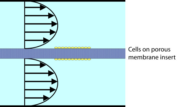
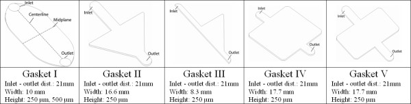
Methods: This study provides a novel chamber design to provide both physiologically-based flow regimes, improvements in control of experimental variables, as well as ease of use compared to commercial chambers. This novel design achieves controlled stresses through five gasket designs and both single- and dual-flow regimes.

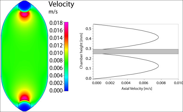
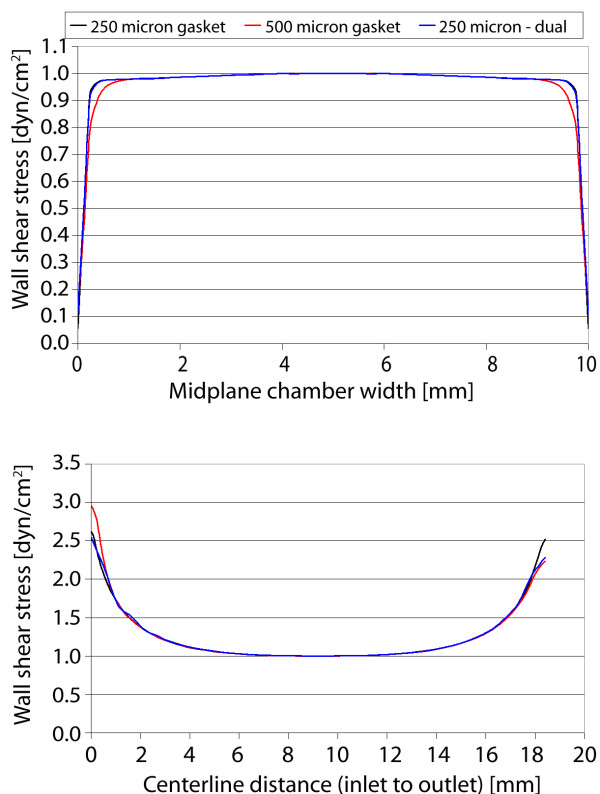
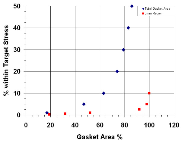
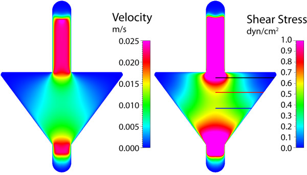
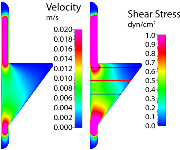
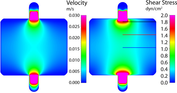
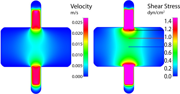
Results: The imparted shear stress within the gasket geometry is well controlled. Fifty percent of the entire area of the 10 x 21 mm universal gasket (Gasket I, designed to impart constant magnitude shear stresses in the center of the chamber where outcome measures are taken), is exposed to target stresses. In the 8 mm diameter circular area at the center of the chamber (where outcome measures are made), over 92% of the area is exposed to the target stress (+/- 2.5%). In addition, other gasket geometries provide specific gradients of stress that vary with distance from the chamber inlet. Bench-top testing of the novel chamber prototype shows improvements, in the ease of use as well as in performance, compared to the other commercial chambers. The design of the chamber eliminates flow deviations due to leakage and bubbles and allows actual flow profiles to better conform with those predicted in computational models.

Conclusion: The novel flow chamber design provides predictable and well defined mechanical forces at the surface of a cell monolayer, showing improvement over previously tested commercial chambers. The predictability of the imparted stress improves both experiment repeatability as well as the accuracy of inter-study comparisons. Carefully controlling the stresses on cells is critical in effectively mimicking in vivo situations. Overall, the improved perfusion flow chamber provides the needed resolution, standardization and in vitro model analogous to in vivo conditions to make the step towards greater use in research and the opportunity to enter the diagnostic and therapeutic market.


Figures

Figure 1
Figure 1
Dual-flow profile schematic. The general schematic for apical and basal flow used in the design of the novel flow chamber, where the cell monolayer is housed between the two fluid reservoirs on either a porous membrane or solid substrate.
Figure 2
Figure 2
Novel flow chamber design. Flow geometry is dictated by the rubber gasket(s), where two polycarbonate cases are used to deliver flow as well as to compress and seal the fluid space. Nylatron thumb screws are used to tighten the chamber, and circular glass coverslips are used to seal flow and provide microscope visualization. Flow is administered through inlet and outlet tubing connected to the barbed inlets/outlets, placed orthogonal to the chamber surface for ease of use with the microscope stage. Left: fabricated flow chamber in use for endothelial studies. A mouse embryonic stem cell line E14Tg2a is pre-differentiated on cover-slips coated with 0.1% gelatin, and then exposed to shear stress of 1.5 – 5 dyn/cm2 to induce endothelial differentiation. Typical experiments are carried out for 1–2 days (courtesy of Professor Horst von Recum). Right: technical drawings of design in dual and single mode.
Figure 3
Figure 3
Gasket designs. (I) Designed to impart constant shear stress to the cell monolayer; (II) symmetric expansion, linear contraction zone for specific stress gradient; (III) asymmetric expansion, linear contraction zone for specific stress gradient; (IV) planar jet geometry for specific stress gradient; (V) shortened planar jet geometry.
Figure 4
Figure 4
Gasket I velocity in single-flow. Maximum axial velocity plane, center of gasket height, for gasket thickness of (A) 250 μm and (B) 500 μm.
Figure 5
Figure 5
Gasket I velocity in dual-flow. (A) Maximum axial velocity plane in dual-flow setup, upper gasket; (B) Velocity profiles for upper and lower gaskets in dual-flow, at intersection of centerline and midplane.
Figure 6
Figure 6
Gasket I shear stress. Wall shear stress on bottom wall of chamber, at location of cell monolayer, for (A) single-flow 250 μm gasket, (B) single-flow 500 μm gasket, and (C) dual-flow 250 μm gasket.
Figure 7
Figure 7
Gasket I shear stress plots. Wall shear stress plotted along chamber midplane (top) and centerline (bottom) for the three cases.
Figure 8
Figure 8
Gasket I area and shear stress range. The percentage of area that is within the specified range of the target shear stress for (a) entire gasket area and (b) an 8 mm region of interest.
Figure 9
Figure 9
Gasket II velocity and shear stress. Maximum axial velocity plane (left), and wall shear stress on chamber bottom (right) with three sampling locations for shear stress profile.
Figure 10
Figure 10
Gasket II shear stress plots. Wall shear stress for the three sampling locations, plotted from the chamber centerline to the wall. High gradients of shear stress are found near the entrance to the expansion zone (line 1), where the imparted stress smooths with increasing distance from the entrance (near midplane).
Figure 11
Figure 11
Gasket III velocity and shear stress. Maximum axial velocity plane (left), and wall shear stress on chamber bottom (right) with three sampling locations for shear stress profile.
Figure 12
Figure 12
Gasket III shear stress plots. Wall shear stress for the three sampling locations, plotted from the chamber centerline to the wall. Similar to Gasket II, however sharp gradients of stress are found near the centerline or left wall of the gasket.
Figure 13
Figure 13
Gasket IV velocity and shear stress. Maximum axial velocity plane (left), and wall shear stress on chamber bottom (right) with three sampling locations for shear stress profile.
Figure 14
Figure 14
Gasket IV shear stress plots. Wall shear stress for the three sampling locations, plotted from the chamber centerline to the wall. High gradients of shear stress are found near the entrance to the expansion zone (line 1), with nearly constant profiles near the midplane (lines 2, 3).
Figure 15
Figure 15
Gasket V velocity and shear stress. Maximum axial velocity plane (left), and wall shear stress on chamber bottom (right) with three sampling locations for shear stress profile.
Figure 16
Figure 16
Gasket V shear stress plots. The magnitudes in stress are decreased from Gasket IV, where the midplane stress (line 3) is more variable as well.

Similar articles

Cited by

References

    1. Albuquerque ML, Flozak AS. Lamellipodial motility in wounded endothelial cells exposed to physiologic flow is associated with different patterns of beta1-integrin and vinculin localization. J Cell Physio. 2003;195:50–60. doi: 10.1002/jcp.10228. - DOI - PubMed
    1. Hung CT, Pollack SR, Reilly TM, Brighton CT. Real-time calcium response of cultured bone cells to fluid flow. Clin Orthop. 1995;313:256–269. - PubMed
    1. Jacobs CR, Yellowley CE, Davis BR, Zhou Z, Cimbala JM, Donahue HJ. Differential effect of steady versus oscillating flow on bone cells. J Biomech. 1998;31:969–976. doi: 10.1016/S0021-9290(98)00114-6. - DOI - PMC - PubMed
    1. Sorkin AM, Dee KC, Knothe Tate ML. "Culture shock" from the bone cell's perspective: emulating physiological conditions for mechanobiological investigations. Am J Physiol Cell Physiol. 2004;287:C1527–36. doi: 10.1152/ajpcell.00059.2004. - DOI - PubMed
    1. Nauman EA, Satcher RL, Keaveny TM, Halloran BP, Bikle DD. Osteoblasts respond to pulsatile fluid flow with short-term increases in PGE(2) but no change in mineralization. J Appl Physiol. 2001;90:1849–1854. - PubMed

Publication types

MeSH terms

LinkOut - more resources