

Functions of bifans in context of multiple regulatory motifs in signaling networks
- PMID: 18178648
- PMCID: PMC2267139
- DOI: 10.1529/biophysj.107.116673
Functions of bifans in context of multiple regulatory motifs in signaling networks
Abstract
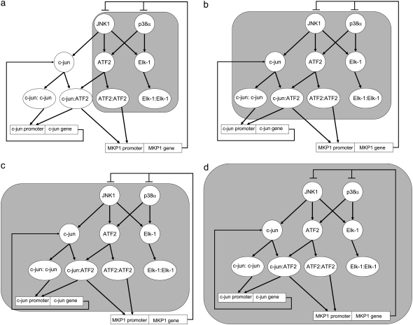
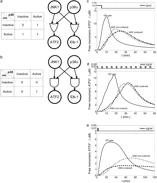
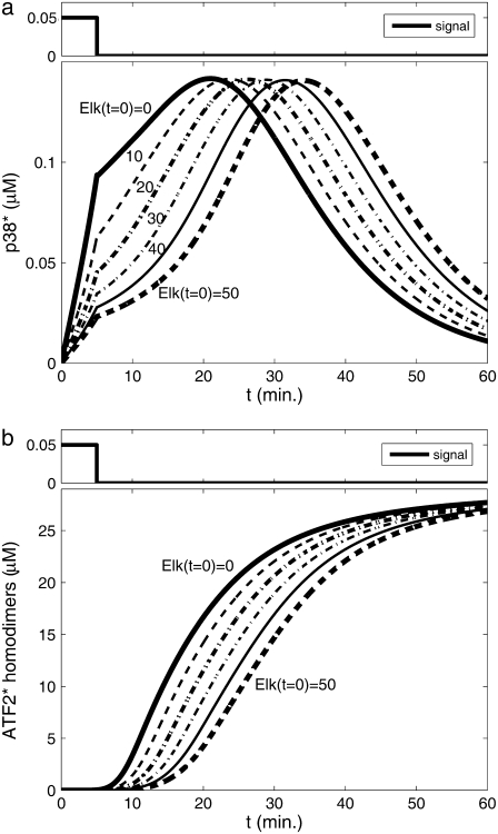
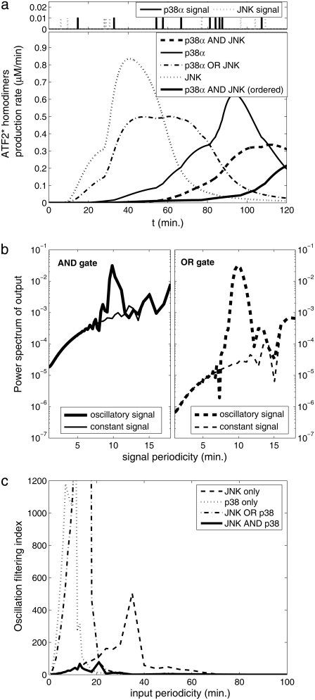
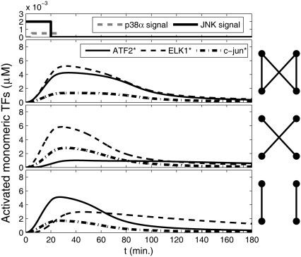
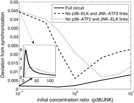
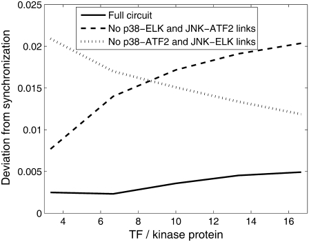
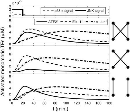
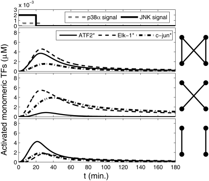
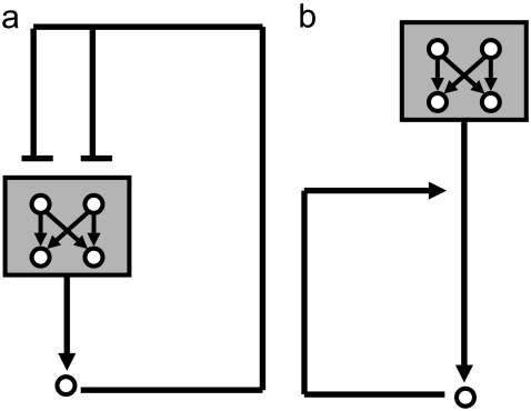
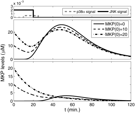
Representation of intracellular signaling networks as directed graphs allows for the identification of regulatory motifs. Regulatory motifs are groups of nodes with the same connectivity structure, capable of processing information. The bifan motif, made of two source nodes directly crossregulating two target nodes, is an overrepresented motif in a mammalian cell signaling network and in transcriptional networks. One example of a bifan is the two MAP-kinases, p38, and JNK that phosphorylate and activate the two transcription factors ATF2 and Elk-1. We have used a system of coupled ordinary differential equations to analyze the regulatory capability of this bifan motif by itself, and when it interacts with other motifs such as positive and negative feedback loops. Our results indicate that bifans provide temporal regulation of signal propagation and act as signal sorters, filters, and synchronizers. Bifans that have OR gate configurations show rapid responses whereas AND gate bifans can introduce delays and allow prolongation of signal outputs. Bifans that have AND gates can filter noisy signal inputs. The p38/JNK-ATF2/Elk-1bifan synchronizes the output of activated transcription factors. Synchronization is a robust property of bifans and is exhibited even when the bifan is adjacent to a positive feedback loop. The presence of the bifan promotes the transcription and translation of the dual specificity protein phosphatase MKP-1 that inhibits p38 and JNK thus enabling a negative feedback loop. These results indicate that bifan motifs in cell signaling networks can contribute to signal processing capability both intrinsically and by enabling the functions of other regulatory motifs.
Figures
Similar articles
-
Network topology determines dynamics of the mammalian MAPK1,2 signaling network: bifan motif regulation of C-Raf and B-Raf isoforms by FGFR and MC1R.FASEB J. 2008 May;22(5):1393-403. doi: 10.1096/fj.07-9100com. Epub 2008 Jan 2. FASEB J. 2008. PMID: 18171696
-
Boolean dynamics of biological networks with multiple coupled feedback loops.Biophys J. 2007 Apr 15;92(8):2975-81. doi: 10.1529/biophysj.106.097097. Epub 2007 Jan 26. Biophys J. 2007. PMID: 17259267 Free PMC article.
-
The effect of negative feedback loops on the dynamics of boolean networks.Biophys J. 2008 Jul;95(2):518-26. doi: 10.1529/biophysj.107.125021. Epub 2008 Mar 28. Biophys J. 2008. PMID: 18375509 Free PMC article.
-
Graph theory and networks in Biology.IET Syst Biol. 2007 Mar;1(2):89-119. doi: 10.1049/iet-syb:20060038. IET Syst Biol. 2007. PMID: 17441552 Review.
-
Systems-level insights into cellular regulation: inferring, analysing, and modelling intracellular networks.IET Syst Biol. 2007 Mar;1(2):61-77. doi: 10.1049/iet-syb:20060071. IET Syst Biol. 2007. PMID: 17441550 Review.
Cited by
-
Introduction to network analysis in systems biology.Sci Signal. 2011 Sep 6;4(190):tr5. doi: 10.1126/scisignal.2001965. Sci Signal. 2011. PMID: 21917719 Free PMC article.
-
Biological Prescience: The Role of Anticipation in Organismal Processes.Front Physiol. 2021 Dec 17;12:672457. doi: 10.3389/fphys.2021.672457. eCollection 2021. Front Physiol. 2021. PMID: 34975512 Free PMC article. Review.
-
A Bifan Motif Shaped by ArsR1, ArsR2, and Their Cognate Promoters Frames Arsenic Tolerance of Pseudomonas putida.Front Microbiol. 2021 Mar 12;12:641440. doi: 10.3389/fmicb.2021.641440. eCollection 2021. Front Microbiol. 2021. PMID: 33776973 Free PMC article.
-
Specification of spatial relationships in directed graphs of cell signaling networks.Ann N Y Acad Sci. 2009 Mar;1158:44-56. doi: 10.1111/j.1749-6632.2008.03748.x. Ann N Y Acad Sci. 2009. PMID: 19348631 Free PMC article.
-
Network, degeneracy and bow tie. Integrating paradigms and architectures to grasp the complexity of the immune system.Theor Biol Med Model. 2010 Aug 11;7:32. doi: 10.1186/1742-4682-7-32. Theor Biol Med Model. 2010. PMID: 20701759 Free PMC article.
References
-
- Albert, R. 2005. Scale-free networks in cell biology. J. Cell Sci. 118:4947–4957. - PubMed
-
- Eisenberg, D., E. M. Marcotte, I. Xenarios, and T. O. Yeates. 2000. Protein function in the post-genomic era. Nature. 405:823–826. - PubMed
-
- Milo, R., S. Shen-Orr, S. Itzkovitz, N. Kashtan, D. Chklovskii, and U. Alon. 2002. Network motifs: simple building blocks of complex networks. Science. 298:824–827. - PubMed
Publication types
MeSH terms
Substances
Grants and funding
LinkOut - more resources
Full Text Sources
Research Materials
Miscellaneous
