. 2008 Mar 7;376(5):1334-47.
doi: 10.1016/j.jmb.2007.12.048. Epub 2008 Jan 3.

Structural Insights into ribosome recycling factor interactions with the 70S ribosome

Affiliations

Structural Insights into ribosome recycling factor interactions with the 70S ribosome

Raj D Pai et al. J Mol Biol. .

Abstract

At the end of translation in bacteria, ribosome recycling factor (RRF) is used together with elongation factor G to recycle the 30S and 50S ribosomal subunits for the next round of translation. In x-ray crystal structures of RRF with the Escherichia coli 70S ribosome, RRF binds to the large ribosomal subunit in the cleft that contains the peptidyl transferase center. Upon binding of either E. coli or Thermus thermophilus RRF to the E. coli ribosome, the tip of ribosomal RNA helix 69 in the large subunit moves away from the small subunit toward RRF by 8 A, thereby disrupting a key contact between the small and large ribosomal subunits termed bridge B2a. In the ribosome crystals, the ability of RRF to destabilize bridge B2a is influenced by crystal packing forces. Movement of helix 69 involves an ordered-to-disordered transition upon binding of RRF to the ribosome. The disruption of bridge B2a upon RRF binding to the ribosome seen in the present structures reveals one of the key roles that RRF plays in ribosome recycling, the dissociation of 70S ribosomes into subunits. The structures also reveal contacts between domain II of RRF and protein S12 in the 30S subunit that may also play a role in ribosome recycling.


Figures

Figure 1
Figure 1
Brief overview of the ribosome recycling process. (A) At the end of the translation cycle, the stop codon occupies the A site. Release Factors (RFs) hydrolyze the polypeptide from peptidyl-tRNA in the P site at this point. The ribosome then exists in a post-termination complex in the classical conformation, i.e. unratcheted state, which then converts to the ratcheted state. (B) RRF binds to the post-termination complex, in the ratcheted state of the ribosome–. (C) EF-G binding to the complex, –, coupled with GTP hydrolysis dissociates the subunits from each other as well as mRNA and tRNA–, –, , . The asterisk indicates that multiple steps occur in the process of subunit dissociation.
Figure 2
Figure 2. Structure of RRF
Crystal structure of T. thermophilus RRF (PDB ID: 1EH1). RRF Domain I consists of a 3-helix bundle (the five helices present in T. thermophilus RRF are designated as: α1, α5, and α6 according to the nomenclature derived from Selmer et al.. Domain II consists of a β/α/β–sheet motif. The approximate location of the flexible hinge between RRF Domains I and II is indicated by the dotted line. For conserved amino acids in RRF across all species (Methods), those that are identical in both E. coli and T. thermophilus RRF are colored red, those that are similar in two species are colored gold, and those that are dissimilar in the two species are colored cyan. Amino acids in grey are not conserved in RRF.
Figure 3
Figure 3. Comparison of E. coli RRF and T. thermophilus RRF binding to E. coli 70S ribosome II in pre-grown ribosome crystals
(A) Schematic representation of the 70S ribosome/RRF complex in the classical conformation, i.e. unratcheted state. All crystallographic analyses in this paper were performed on this complex. (B) Fobs - Fobs difference electron density map comparing the 70S ribosome/E. coli RRF complex to the apo-70S ribosome (Methods) is shown at 6 Å resolution. In this figure, T. thermophilus RRF (pdb ID: 1EH1) is used as a homology model for E. coli RRF and is docked into the positive difference density. The approximate locations of the P site and A site are indicated by lines near H69 in the figure. (C) Fobs - Fobs difference electron density map comparing the 70S ribosome/T. thermophilus RRF complex to the apo-70S ribosome (Methods) is shown at 6 Å resolution. (D) Fobs - Fobs difference electron density map comparing the 70S ribosome/T. thermophilus RRF complex to the 70S ribosome/E. coli RRF complex at 6 Å resolution. In panel (B), positive density (blue) and negative density (red) are at +/−2.5 standard deviations from the mean. In panels (C) and (D), positive density (blue) and negative density (red) are contoured at +/− 3 standard deviations from the mean, respectively. RRF is shown (blue), as are 16S rRNA (cyan) and 23S rRNA (green). The approximate location of RRF Domain II (DII) is shown. The direction of view is shown by the icon to the right in panel (B).
Figure 4
Figure 4. E. coli RRF in complex with ribosome II in crystals grown from pre-formed RRF ribosome complexes
(A) Fobs - Fobs difference electron density map comparing 70S ribosomes co-crystallized with E. coli RRF to 70S ribosomes in pre-grown crystals subsequently soaked with T. thermophilus RRF, at 8 Å resolution. Since no significant difference density is evident, the co-crystallized E. coli RRF 70S ribosome complex is nearly identical to the complex formed by soaking the RRF into the pre-formed crystals. (B) Fobs - Fobs difference electron density map comparing 70S ribosomes co-crystallized with E. coli RRF to the apo-70S ribosome, at 8 Å resolution. Positive density (blue) and negative density (red) are at +/− 3 standard deviations from the mean, respectively. Elements in the ribosome and RRF are colored as in Figure 3. The approximate location of RRF Domain II (DII) is shown. The direction of view is shown by the icon in Figure 3B.
Figure 5
Figure 5. The movement of helix H69 upon RRF binding
(A) Fobs - Fobs difference electron density map comparing the 70S ribosome/T. thermophilus RRF complex to the apo-70S ribosome (ribosome I), at 6 Å resolution. (B) Fobs - Fobs difference electron density map comparing the 70S ribosome/T. thermophilus RRF complex to the apo-70S ribosome (ribosome I), at 3.5 Å resolution. (C) Close-up of interactions between H69-I and T. thermophilus RRF Domain I in ribosome I. The molecular surface of H69 at the interface with RRF is shown. The gold spheres are the Cα positions of the residues in RRF that likely contact H69. (D) Fobs - Fobs difference electron density map comparing the 70S ribosome/T. thermophilus RRF complex to the apo-70S ribosome (ribosome II) is shown, at 3.5 Å resolution. (E) Fobs - Fobs difference electron density map comparing the soaked 70S ribosome/E. coli RRF complex to the apo-70S ribosome (ribosome I) is shown, at 6 Å resolution. (F) Fobs - Fobs difference electron density map comparing the co-crystallized 70S ribosome/E. coli RRF complex to the apo-70S ribosome (ribosome I) is shown, at 8 Å resolution. In panels (A) and (B), positive density (blue) and negative density (red) are at +/−2.5 standard deviations from the mean, respectively. In panel (D), positive density (blue) and negative density (red) is contoured at +/− 3 standard deviations from the mean, respectively. In panels (E) and (F), positive density (blue) and negative density (red) are at +/− 2.2 standard deviations from the mean, respectively. Elements in the ribosome and RRF are colored as in Figure 3. The approximate location of RRF Domain II (DII) is shown. The direction of view is shown by the icon in Figure 3B.
Figure 6
Figure 6. Temperature factors of helix H69-I in the 70S ribosome structures
(A) Temperature factors in H69-I in the 70S ribosome/T. thermophilus RRF complex. RRF is in grey with amino acids in close proximity to H69 highlighted in magenta. (B) Temperature factors in H69-I in the apo-70S ribosome.
Figure 7
Figure 7. 3Fobs - 2Fcalc electron density maps at 3.3 Å resolution detailing the interaction of T. thermophilus RRF Domain I with the ribosome
(A) T. thermophilus RRF Domain I docked into 3Fobs - 2Fcalc difference electron density (blue), in ribosome II. (B) T. thermophilus RRF Domain I docked into 3Fobs - 2Fcalc difference electron density (blue), in ribosome I. The position of Domain II is based on rigid-body refinement of the domain against the crystallographic data (see Methods). In panels (A) and (B), the electron density is contoured at +/− 1.2 standard deviations from the mean, respectively.
Figure 8
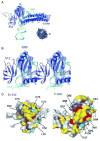
Figure 8. Interaction of RRF Domain II with protein S12
(A) Fobs -Fobs difference electron density map comparing the 70S ribosome/T. thermophilus RRF complex to the 70S ribosome/E. coli RRF complex (ribosome II), at 6 Å resolution. T. thermophilus RRF Domain II refined as a rigid body (Methods) is shown docked into the difference density. Ribosomal protein S12 (dark purple) and h44 in 16S rRNA (cyan) are also shown. Positive density (blue) near RRF is shown, at +2 standard deviations from the mean. The direction of view is shown by the icon to the right. (B) Stereo view of the interaction between T. thermophilus RRF Domain II and protein S12. (C) Evolutionary trace analysis of RRF and protein S12. The interaction in (A) has been “opened” to yield the surface interaface of S12 (left, same orientation as in panel A) and RRF (right, rotated 180° around the vertical axis relative to panel A). Residues that are conserved and buried are colored dark blue on the molecular surface representations. Residues that are conserved and exposed are colored light blue. Residues that are class-specific and buried are colored red. Residues that are class-specific and exposed are colored gold. The approximate interface between T. thermophilus RRF Domain II and E. coli protein S12 is indicated by the dotted ellipses.

References

    1. Hirokawa G, Demeshkina N, Iwakura N, Kaji H, Kaji A. The ribosome-recycling step: consensus or controversy? Trends Biochem Sci. 2006;31:143–9. - PubMed
    1. Hirashima A, Kaji A. Role of elongation factor G and a protein factor on the release of ribosomes from messenger ribonucleic acid. J Biol Chem. 1973;248:7580–7. - PubMed
    1. Hirokawa G, Nijman RM, Raj VS, Kaji H, Igarashi K, Kaji A. The role of ribosome recycling factor in dissociation of 70S ribosomes into subunits. RNA. 2005;11:1317–28. - PMC - PubMed
    1. Janosi L, Shimizu I, Kaji A. Ribosome recycling factor (ribosome releasing factor) is essential for bacterial growth. Proc Natl Acad Sci U S A. 1994;91:4249–53. - PMC - PubMed
    1. Janosi L, Mottagui-Tabar S, Isaksson LA, Sekine Y, Ohtsubo E, Zhang S, Goon S, Nelken S, Shuda M, Kaji A. Evidence for in vivo ribosome recycling, the fourth step in protein biosynthesis. EMBO J. 1998;17:1141–51. - PMC - PubMed

Publication types

MeSH terms

LinkOut - more resources