. 2008 Feb;4(2):e30.
doi: 10.1371/journal.pcbi.0040030.

Stimulus design for model selection and validation in cell signaling

Affiliations

Stimulus design for model selection and validation in cell signaling

Joshua F Apgar et al. PLoS Comput Biol. 2008 Feb.

Abstract

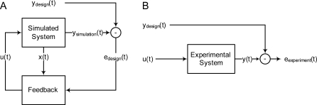
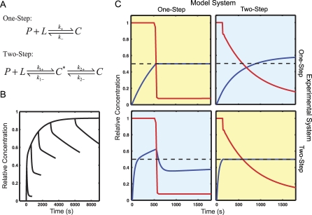
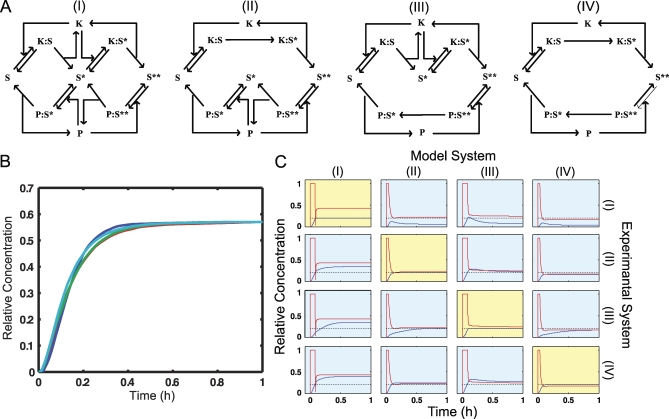
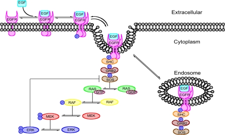
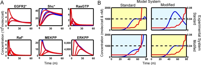
Mechanism-based chemical kinetic models are increasingly being used to describe biological signaling. Such models serve to encapsulate current understanding of pathways and to enable insight into complex biological processes. One challenge in model development is that, with limited experimental data, multiple models can be consistent with known mechanisms and existing data. Here, we address the problem of model ambiguity by providing a method for designing dynamic stimuli that, in stimulus-response experiments, distinguish among parameterized models with different topologies, i.e., reaction mechanisms, in which only some of the species can be measured. We develop the approach by presenting two formulations of a model-based controller that is used to design the dynamic stimulus. In both formulations, an input signal is designed for each candidate model and parameterization so as to drive the model outputs through a target trajectory. The quality of a model is then assessed by the ability of the corresponding controller, informed by that model, to drive the experimental system. We evaluated our method on models of antibody-ligand binding, mitogen-activated protein kinase (MAPK) phosphorylation and de-phosphorylation, and larger models of the epidermal growth factor receptor (EGFR) pathway. For each of these systems, the controller informed by the correct model is the most successful at designing a stimulus to produce the desired behavior. Using these stimuli we were able to distinguish between models with subtle mechanistic differences or where input and outputs were multiple reactions removed from the model differences. An advantage of this method of model discrimination is that it does not require novel reagents, or altered measurement techniques; the only change to the experiment is the time course of stimulation. Taken together, these results provide a strong basis for using designed input stimuli as a tool for the development of cell signaling models.


Conflict of interest statement

Competing interests. The authors have declared that no competing interests exist.

Figures

Figure 1
Figure 1. Schematic of Experimental Design
(A) A feedback controller is used to solve for the stimulus u(t) that will drive the model system outputs y simulation(t) to follow the design trajectory y design(t). The inputs to the feedback controller are the deviation from the desired trajectory e design(t) as well as the model state x(t). (B) The designed stimulus can be applied to an unknown experimental system to assess the quality of the model. A stimulus based on a good model should be able to drive the experimental system output y(t) through the design trajectory.
Figure 2
Figure 2. Analysis of Monovalent Antibody Binding
(A) Two models of monovalent antibody binding, a one-step version with no intermediate, and a two-step version with an association intermediate C *. (B) The results of six simulated experiments are shown as designed in [3]. Each trace is the response of the system to a square pulse of ligand concentration. The width of the pulse varies from 400 s to 6,000 s. The pronounced elbow in the middle curves is indicative of the two-state model. The one-step model cannot have compound off kinetics. (C) The set of experiments designed by this algorithm as well as simulated results are shown. Each pulse was designed to produce a level output when applied to the correct model (yellow boxes), which was observed, and produced a distinctly different result when applied to the other model (blue boxes). The red lines are the inputs (unbound L) the blue lines are the output (C or C + C *). The smaller the gap between the blue and the black dashed line the better the model fits the real system. Looking across one row shows a pair of experiments that would be run together.
Figure 3
Figure 3. Analysis of MAPK Mechanisms
(A) Four alternative MAPK reaction schemes are shown. These correspond to all combinations of processive and distributive kinase and phosphatase mechanisms. Model I is the canonical all-distributive mechanism. For each model the input is the concentration of activated kinase (K) and the output is the doubly phosphorylated substrate (S**). (B) All four MAPK models respond in very similar fashion to a step increase in kinase input (u = 1). (C) A set of 16 model-selection experiments. Each row is a different experimental system and each column is a different candidate model. Red lines are inputs (activated K), blue lines are outputs (S**), and the black dashed line is the design output trajectory. The experiments on the diagonal show that the correct model can control the system. The off-diagonal experiments show that the wrong model does a worse job. This difference can be used to select the correct model.
Figure 4
Figure 4. Schematic of EGF-Induced Signaling
This schematic shows the major steps in EGFR signaling. At the top of the pathway ligand binds to the receptor and induces receptor dimerization and activation. The signal is then transduced through a series of adaptor proteins SHC, GRB2, and SOS, which in turn activates the MAPK cascade RAF, MEK and ERK. There are two negative feedback loops: internalization and degradation of the receptor complex, and ERK deactivation of SOS.
Figure 5
Figure 5. Comparison of Step Experiment to Designed Experiment for EGFR Pathway with Original and Modified Models
(A) Both models respond similarly but not identically to a step input in EGF over a range of concentrations. The red lines are the outputs of the modified model and the blue lines are the outputs of the standard model. Often the blue lines are not visible because they are under the red lines. (B) Two designed dynamic stimuli were applied to two models of the EGFR pathway. The red lines show the input (EGF) concentration as a function of time. The blue lines show the output concentrations (ERKpp). The dashed black line shows the target ERKpp concentration. The controller for the standard model is unable to keep the output level high and saturates. In contrast, the modified model requires a more gradual increase in the input and can control the experiment over the entire time course. In both cases the controller based on the wrong model performs worse that the controller based on the correct model.

References

    1. Kitano H. Systems biology: A brief overview. Science. 2002;295:1662–1664. - PubMed
    1. Kremling A, Saez-Rodriguez J. Systems biology—An engineering perspective. J Biotechnol. 2007;129:329–351. - PubMed
    1. Lipschultz CA, Li Y, Smith-Gill S. Experimental design for analysis of complex kinetics using surface plasmon resonance. Methods. 2000;20:310–318. - PubMed
    1. Box GEP, Hill WJ. Discrimination among mechanistic models. Technometrics. 1967;9:57–71.
    1. Asprey SP, Macchietto S. Designing robust optimal dynamic experiments. J Process Contr. 2002;12:545–556.

Publication types