. 2009 Mar 15;88(4):1010-21.
doi: 10.1002/jbm.a.31935.

Interfaces in graded coatings on titanium-based implants

Affiliations

Interfaces in graded coatings on titanium-based implants

S Lopez-Esteban et al. J Biomed Mater Res A. .

Abstract

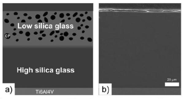
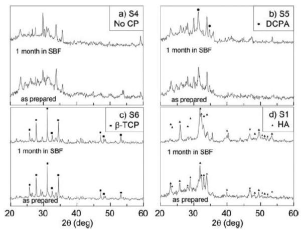
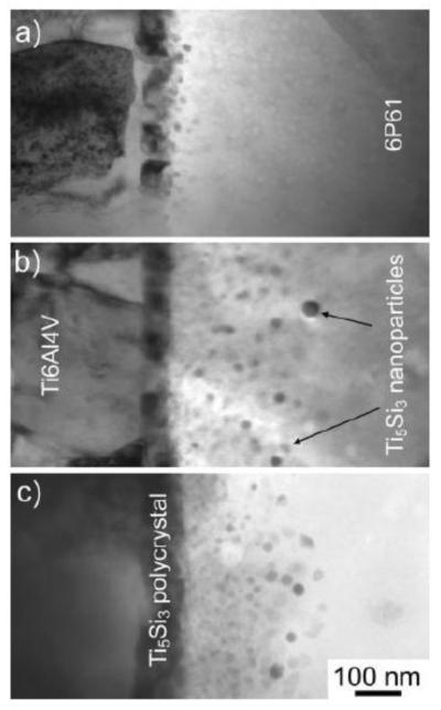
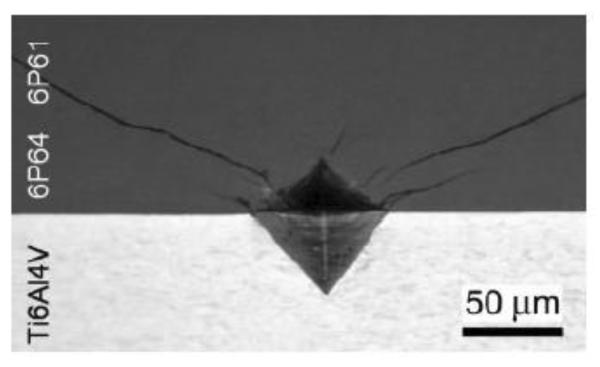
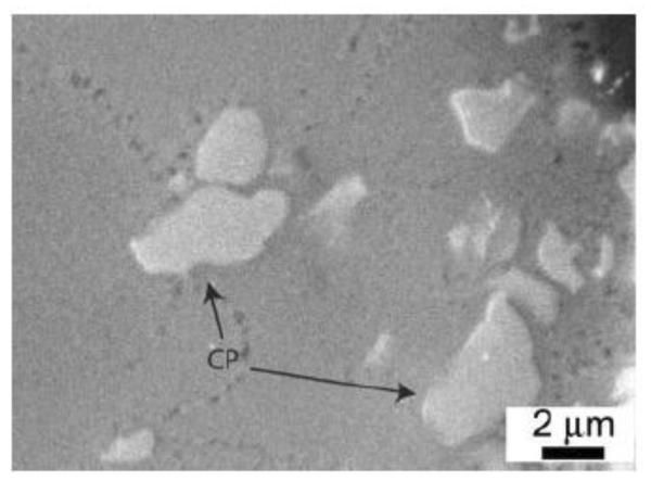
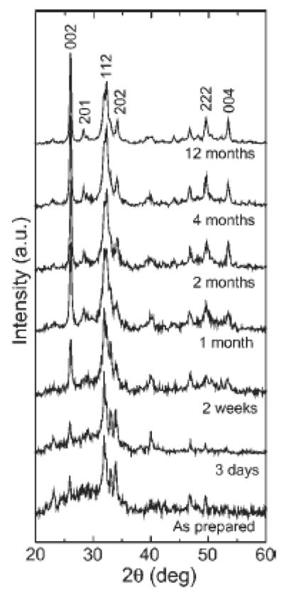
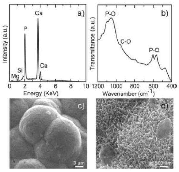
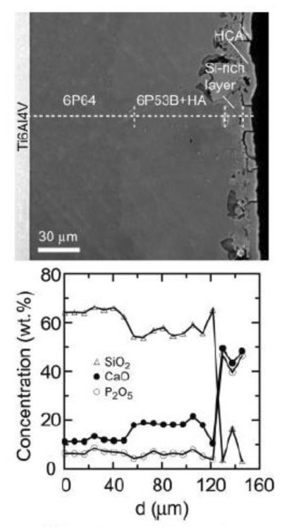
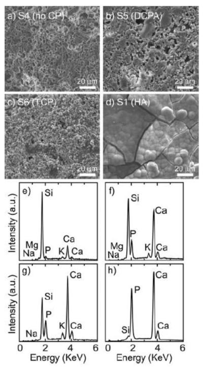
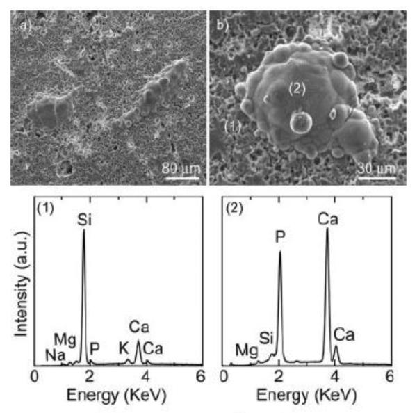
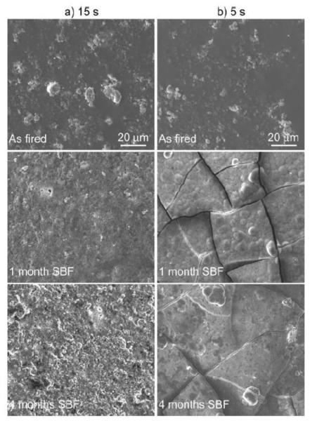
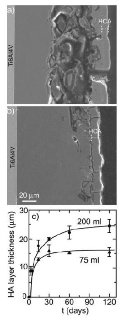
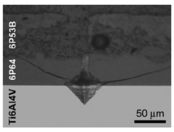
Graded bilayered glass-ceramic composite coatings on Ti6Al4V substrates were fabricated using an enameling technique. The layers consisted of a mixture of glasses in the CaO-MgO-Na(2)O-K(2)O-P(2)O(5) system with different amounts of calcium phosphates (CPs). Optimum firing conditions have been determined for the fabrication of coatings having good adhesion to the metal, while avoiding deleterious reactions between the glass and the ceramic particles. The final coatings do not crack or delaminate. The use of high-silica layers (>60 wt % SiO(2)) in contact with the alloy promotes long-term stability of the coating; glass-metal adhesion is achieved through the formation of a nanostructured Ti(5)Si(3) layer. A surface layer containing a mixture of a low-silica glass ( approximately 53 wt % SiO(2)) and synthetic hydroxyapatite particles promotes the precipitation of new apatite during tests in vitro. The in vitro behavior of the coatings in simulated body fluid depends both on the composition of the glass matrix and the CP particles, and is strongly affected by the coating design and the firing conditions.


Figures

Figure 1
Figure 1
(a) Schematic showing the design of the bilayered coatings, that is, a first layer of a high-silica glass in contact with the alloy and a second surface layer consisting of a mixture of a lower-silica glass and CP particles. (b) SEM micrograph of polished cross-section of sample S1, showing the glass density as well as the absence of gas bubbles or cracks.
Figure 2
Figure 2
XRD of the surface of S4 (glass surface layer 6P53B with no phosphate particles) showing the main crystalline phases found after firing: (▽) sodium calcium phosphate, (◆) sodium calcium silicate, and (◯) diopside.
Figure 3
Figure 3
XRD of the surface of different coatings with and without addition of CP particles. (a) has been added for comparison purposes and the corresponding peaks have been labeled in detail in Figure 2. In (b), the two peaks of DCPA have been labeled; the remaining peaks correspond to the glass surface. Peaks corresponding to β-TCP and HA are labeled in (c) and (d), respectively.
Figure 4
Figure 4
TEM images of glass 6P61/Ti6Al4V interfaces annealed at 800°C for (a) 5 s, (b) 20 s, and (c) 30 s, respectively, showing the presence of a Ti5Si3 interfacial layer consisting of two regions: a continuous polycrystalline layer in contact with the alloy and a region with Ti5Si3 nanoparticles dispersed in the glass.
Figure 5
Figure 5
Vickers indentation at the glass S3/Ti6Al4V interface performed using a 1-kg load in ambient air. The cracks do not propagate along the interface, but rather tend to be driven into the glass. The coating did not delaminate qualitatively indicating good glass-metal adhesion. The same behavior was found in all the samples.
Figure 6
Figure 6
Cross-section of sample S6 (6P64/6P53B + 5%TCP) etched with 5 vol % HF acid for 15 s. No reaction layer can be observed between the calcium phosphate particles and the glass.
Figure 7
Figure 7
XRD diffraction patterns of the surface of sample S1 after immersion in SBF for up to 12 months. The main crystalline phase is carbonated hydroxyapatite [HCA, Ca10(PO4)3(CO3)3(OH)2)], whose peaks are indexed on the figure. The relative intensity of the peaks suggests that the crystals are growing with the c-axis oriented preferentially perpendicular to the coating surface.
Figure 8
Figure 8
EDS analysis (a), FTIR analysis (b), and SEM micrographs (c and d) of the apatite crystals precipitated on the surface of S1 (6P64/6P53B + 5% HA) after 4 months in SBF. The FTIR analysis shows the characteristic HCO3 vibration bands corresponding to carbonated hydroxyapatite (HCA).
Figure 9
Figure 9
SEM micrograph and associated EDS line analysis of a cross-section of S1 after 1 month in SBF.
Figure 10
Figure 10
SEM micrographs (a–d) and EDS analysis (e–h) of the surface of samples S1, S4, S5, and S6, respectively, soaked in SBF for 1 month. Apatite has precipitated on the coatings with synthetic HA particles, whereas only different degrees of glass corrosion and dissolution can be observed in samples with DCPA, β-TCP and without CP additions.
Figure 11
Figure 11
SEM micrograph of the surface of the coating with no addition of CP particles (S4) after being soaked in SBF for 6 months (a) and detail of isolated precipitate (b). EDS analysis of the surface (1) and a precipitate (2) show that they correspond to glass and apatite, respectively.
Figure 12
Figure 12
SEM micrographs of the surface of coatings containing a layer consisting of 6P53B glass and 5 wt % HA fired for 15 s (a) and 5 s (b) at 820°C (S1 and S8, respectively) after immersion in SBF for different times. The coatings exhibit different stages of glass corrosion, but apatite does not precipitate in the samples fired for 15 s. An apatite layer has precipitated in the sample fired for 5 s, where drying cracks are clearly visible.
Figure 13
Figure 13
SEM micrographs of the cross-sections of S1 after being immersed for 1 month in (a) 200 mL SBF and (b) 75 mL SBF. (c) Time evolution of the thickness of the precipitated apatite layer for samples immersed in 75 or 200 mL SBF. Precipitation of apatite stops after 1 month for the sample immersed in 75 mL.
Figure 14
Figure 14
Vickers indentation performed using a 1-kg load in ambient air at the glass S1/Ti6Al4V interface after soaked in simulated body fluid for 2 months. Even after in vitro tests, the cracks do not propagate along the interface, but rather tend to be driven into the glass. The coating did not delaminate qualitatively indicating good glass-metal adhesion. The same behavior was found in all the samples.

Similar articles

Cited by

References

    1. Hench LL. The story of bioglass. J Mater Sci Mater Med. 2006;17:967–978. Links. - PubMed
    1. Ma J, Chen CZ, Yao L, Bao QH. Characterization of some methods of preparation for bioactive glass coating on implants. Surf Rev Lett. 2006;13:93–102. Links.
    1. Zhao YF, Chen CZ, Wang DG. The current techniques for preparing bioglass coatings. Surf Rev Lett. 2005;12:505–513. Links.
    1. Yilmaz S, Ipek M, Celebi GF, Bindal C. The effect of bond coat on mechanical properties of plasma-sprayed Al2O3 and Al2O3-13 wt% TiO2 coatings on AISI 316L stainless steel. Vacuum. 2005;77:315–321. Links.
    1. Li P, deGroot K, Kokubo T. Bioactive Ca-10(PO4)(6)(OH)2-TiO2 composite coating prepared by sol-gel process. J Sol-Gel Sci Technol. 1996;7:27–34. Links.

Publication types

LinkOut - more resources