. 2008 Jun;118(6):1031-9.
doi: 10.1097/MLG.0b013e31816b309e.

Clinical validation of percutaneous cochlear implant surgery: initial report

Affiliations

Clinical validation of percutaneous cochlear implant surgery: initial report

Robert Frederick Labadie et al. Laryngoscope. 2008 Jun.

Abstract

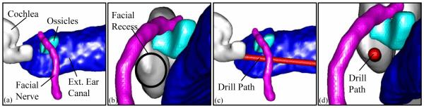
Objective: Percutaneous cochlear implant surgery consists of a single drill path from the lateral mastoid cortex to the cochlea via the facial recess. We sought to clinically validate this technique in patients undergoing traditional cochlear implant surgery.

Study design: Prospective clinical trial.

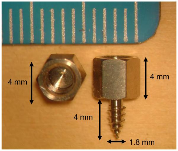
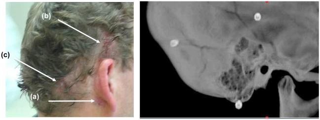
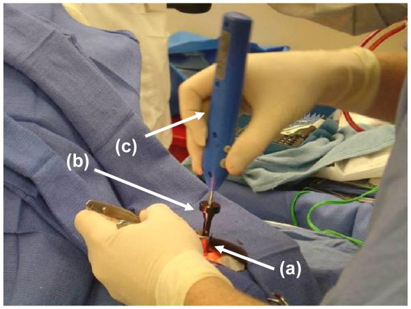
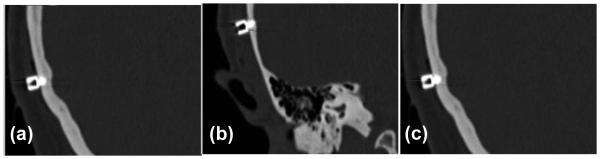
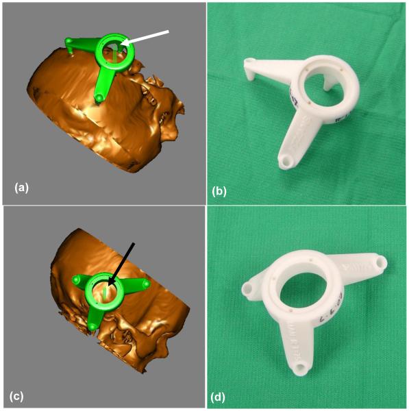
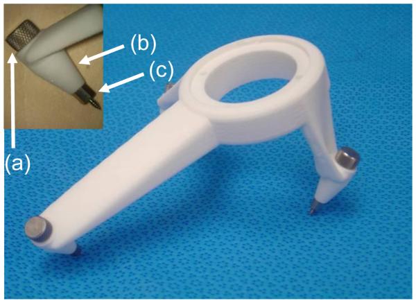
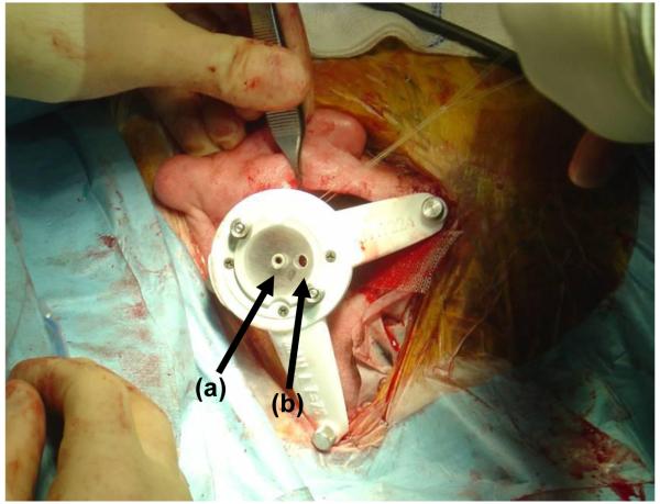
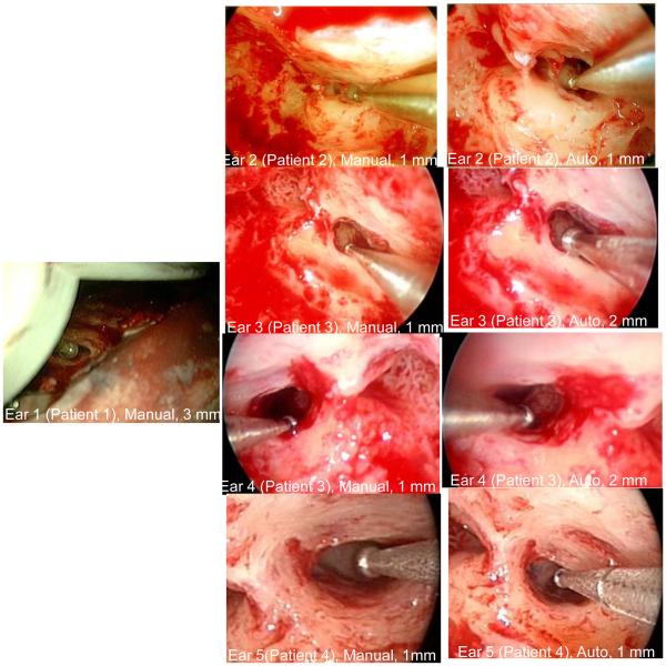
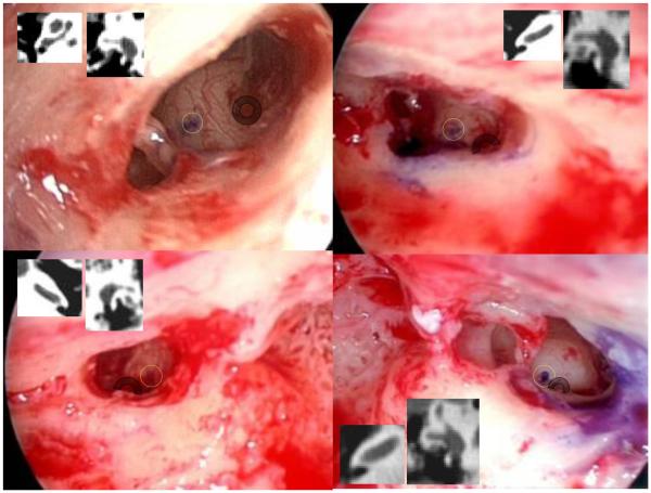
Methods: After institutional regulatory board-approved protocols, five ears were studied via the following steps. 1) In the clinic under local anesthesia, bone-implanted anchors were placed surrounding each mastoid. 2) Temporal-bone computed tomography (CT) scans were obtained. 3) On the CT scans, paths were planned from the lateral mastoid cortex, through the facial recess, to the basal turn of the cochlea both "manually" and "automatically" using computer software. 4) Customized microstereotactic frames were rapid-prototyped to serve as drill guides constraining the drill to follow the appropriate path. 5) During cochlear implant surgery, after drilling of the facial recess, drill guides were mounted on the bone-implanted anchors. 6) Accuracy of paths was assessed via intraoperative photodocumentation.

Results: All surgical paths successfully traversed the facial recess and hit the basal turn of the cochlea. Distance in millimeters (average +/- SD) from the midpoint of the drill to the facial nerve was 1.18 +/- 0.68 for the "manual" path and 1.24 +/- 0.44 mm for the "automatic" path and for the chorda tympani 0.986 +/- 0.48 for the "manual" path and 1.22 +/- 0.62 for the "automatic" path.

Conclusions: Percutaneous cochlear implant access using customized drill guides based on preoperative CT scans and image-guided surgery technology can be safely accomplished.


Figures

Figure 1
Figure 1
Anchor. Left sample shown is from the top. Right sample is shown from the side. The anchor is titanium with a self-tapping screw. The hole at the upper end has female threads to which a bolt can be attached. The bolt connects the drill guide rigidly to a set of these anchors. The smaller markings on the ruler are millimeters.
Figure 2
Figure 2
Anchor positioning. After anchor insertion and skin closed. Locations as named in the text (a) “Mastoid”, (b) “Suprahelix”, (c) “Posterior”.
Figure 3
Figure 3
Anchor insertion. (a) Nasal speculum maintains exposure. (b) Waypoint driver passes through speculum to attach to anchor (not visible). (c) Osteomed electric driver (model 450-0600) inserted into Waypoint driver provides torque.
Figure 4
Figure 4
CT images of three anchors surrounding the left ear. The positions are, as described in the text, (a) Mastoid, (b) Suprahelix, and (c) Posterior.
Figure 5
Figure 5
Example of automatically planned drill path for a right ear. (a) View from posterior-to-anterior. (b) View through facial recess. (c) Same view as (a) but with drill path (1mm diameter) shown. (d) Same view as (b) but with drill path shown.
Figure 6
Figure 6
Drill guide as designed and as a fabricated device. (a) Left ear design, (b) Left ear device, (c) Right ear design, (d) Right ear device. The arrows point to pairs of parallel lines that represent the planned drill paths. The distance between the lines of a pair are equal to the planned drill width (1mm).
Figure 7
Figure 7
The drill guide. A bolt (a) passes through a hole in each foot (b) attaching the foot to an anchor (c), as shown in the inset at the upper left.
Figure 8
Figure 8
Customized drill guide after attachment to the three anchors in the operating room. (a) Entry for drill bit. (b) Entry for endoscope (Hopkins rod). Images in Figure Figure 10 were acquired with the Hopkins rod.
Figure 9
Figure 9
Intraoperative Validation. Each image shows a sham drill bit (diameter noted under each picture) that safely traversed the facial recess. “Manual” means that a manual plan was used. “Automatic” means that the plan based on the computer algorithm was used. No automatic validation was possible for Ear 1 (see text).
Figure 10
Figure 10
The positions of the cochleostomy for each path are shown as a purple spot on the lateral wall of the cochlea. Transparent yellow circles have been added to highlight this position while transparent grey annuli overlie the round window niche. Inset within each panel are the corresponding axial and coronal scans showing boney overhand of the round window. (Note: No data is presented for the first ear as the technique was developed after the first surgery.)

References

    1. Attwood SE, Hill AD, Mealy K. A prospective comparison of laparoscopic versus open cholecystectomy. Ann R Coll Surg Engl. 1992;74(6):397–400. - PMC - PubMed
    1. Soper NJ, Barteau JA, Clayman RV, Ashley SW. Comparison of early postoperative results for laparoscopic versus standard open cholecystectomy. Surg Gynecol Obstet. 1992;174(2):114–118. - PubMed
    1. Vierra M. Minimally invasive surgery. Annu Rev Med. 1995;46:147–158. - PubMed
    1. Messerklinger W. Endoscopy of the nose. Urban&Schwarzenberg (Baltimore, Munich) 1978
    1. Draf W. Therapeutic endoscopy of the paranasal sinuses. Endoscopy. 1978;10(4):247–254. - PubMed

Publication types