

The acoustic lens design and in vivo use of a multifunctional catheter combining intracardiac ultrasound imaging and electrophysiology sensing
- PMID: 18407850
- PMCID: PMC2756724
- DOI: 10.1109/TUFFC.2008.685
The acoustic lens design and in vivo use of a multifunctional catheter combining intracardiac ultrasound imaging and electrophysiology sensing
Abstract
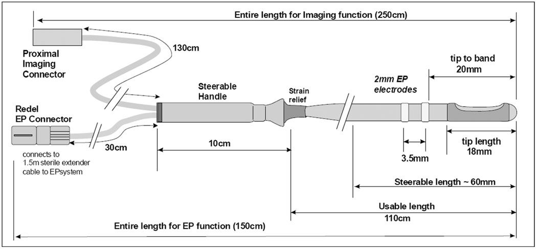
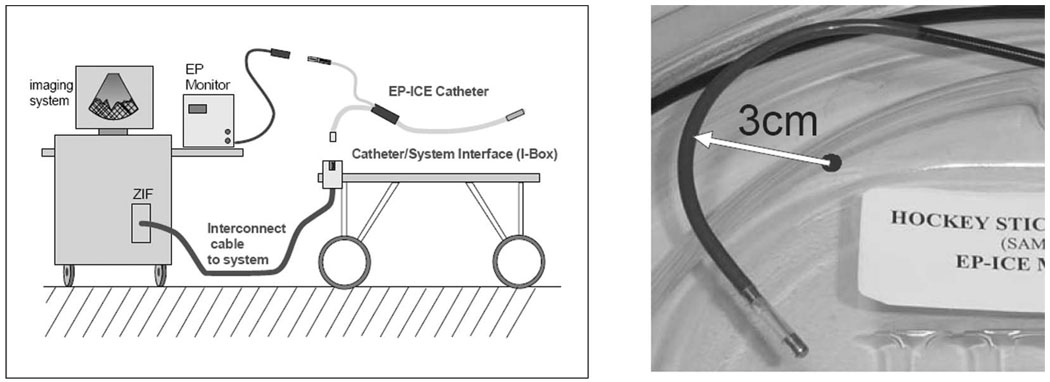
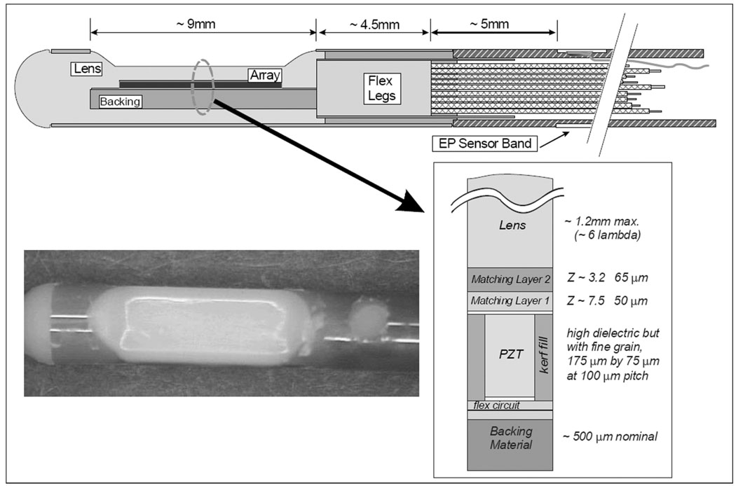
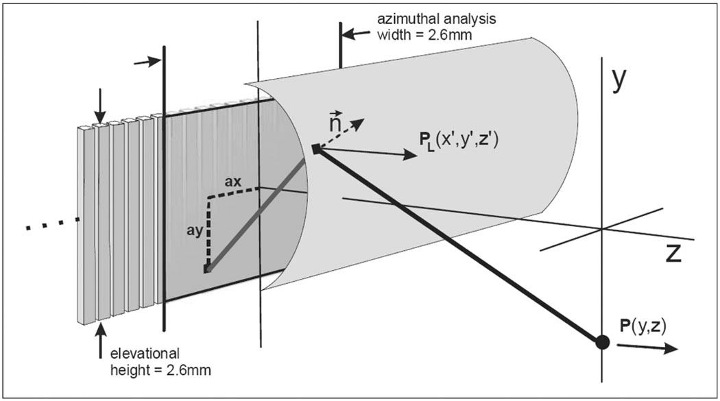
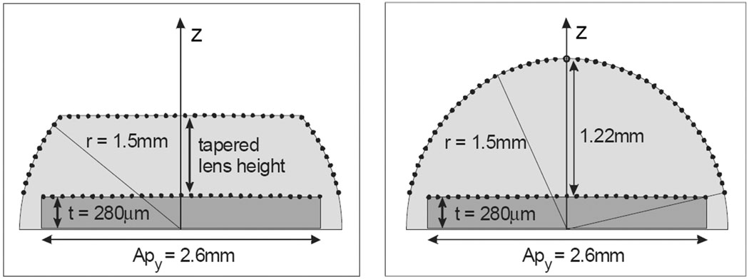
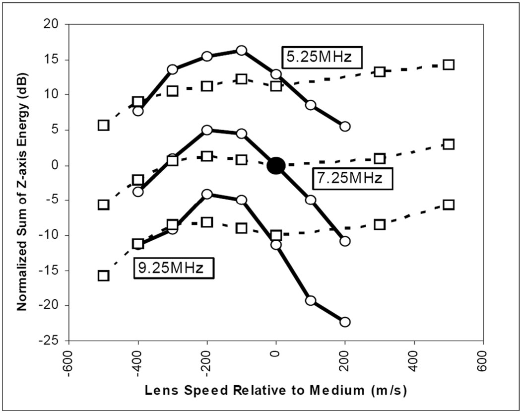
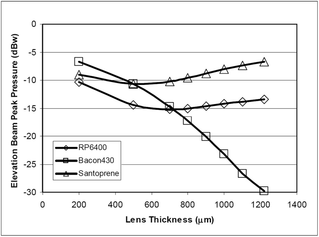
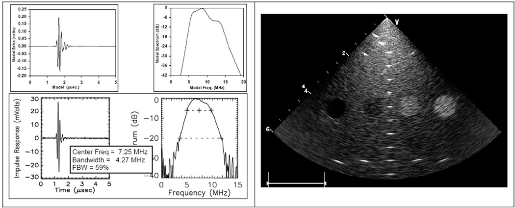
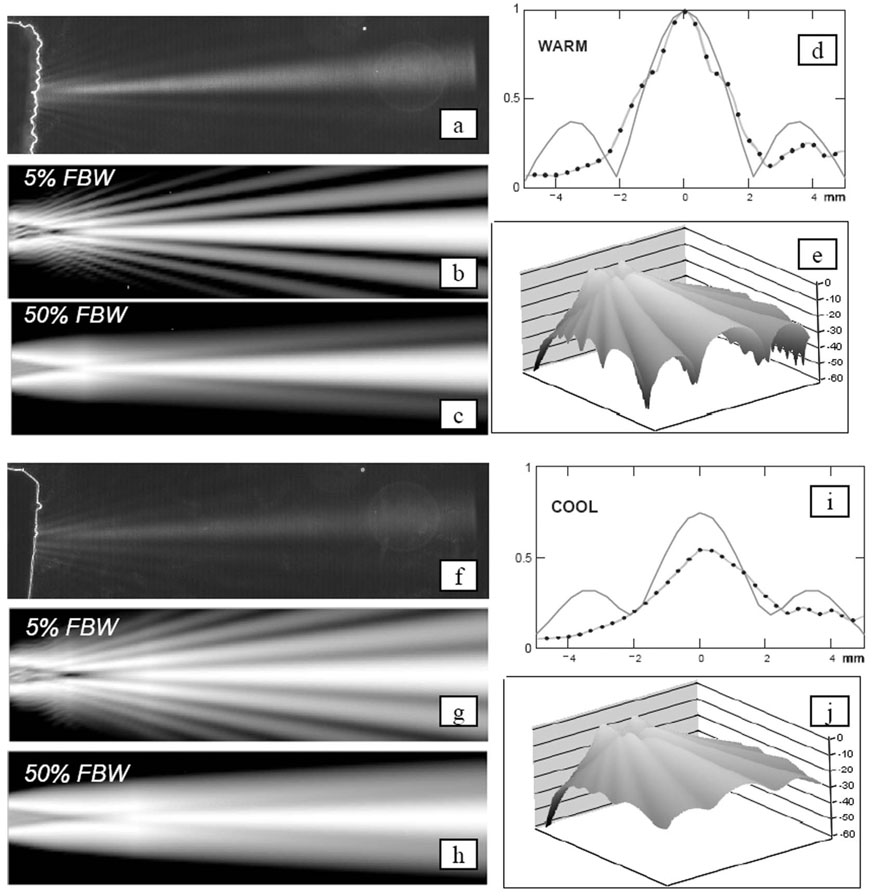
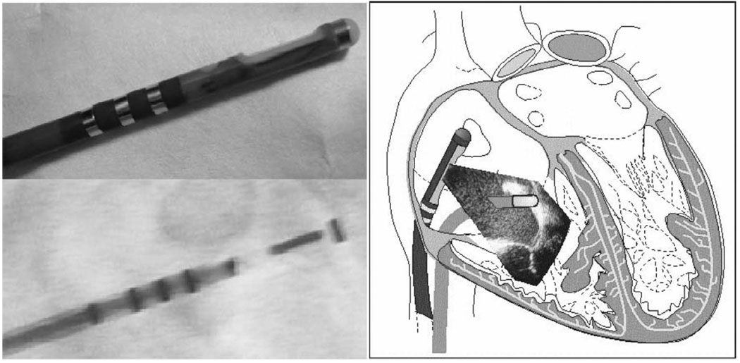
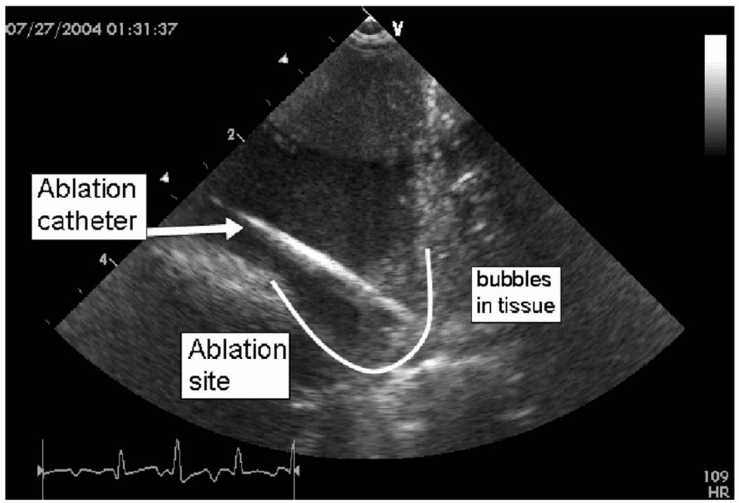
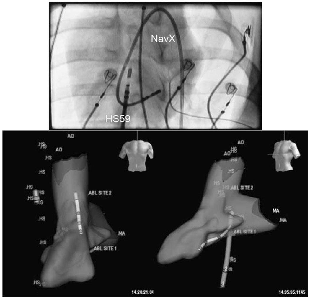
A multifunctional 9F intracardiac imaging and electrophysiology mapping catheter was developed and tested to help guide diagnostic and therapeutic intracardiac electrophysiology (EP) procedures. The catheter tip includes a 7.25-MHz, 64-element, side-looking phased array for high resolution sector scanning. Multiple electrophysiology mapping sensors were mounted as ring electrodes near the array for electrocardiographic synchronization of ultrasound images. The catheter array elevation beam performance in particular was investigated. An acoustic lens for the distal tip array designed with a round cross section can produce an acceptable elevation beam shape; however, the velocity of sound in the lens material should be approximately 155 m/s slower than in tissue for the best beam shape and wide bandwidth performance. To help establish the catheter's unique ability for integration with electrophysiology interventional procedures, it was used in vivo in a porcine animal model, and demonstrated both useful intracardiac echocardiographic visualization and simultaneous 3-D positional information using integrated electroanatomical mapping techniques. The catheter also performed well in high frame rate imaging, color flow imaging, and strain rate imaging of atrial and ventricular structures.
Figures
Similar articles
-
Experimental studies with a 9F forward-looking intracardiac imaging and ablation catheter.J Ultrasound Med. 2009 Feb;28(2):207-15. doi: 10.7863/jum.2009.28.2.207. J Ultrasound Med. 2009. PMID: 19168770 Free PMC article.
-
Multifunctional catheters combining intracardiac ultrasound imaging and electrophysiology sensing.IEEE Trans Ultrason Ferroelectr Freq Control. 2008 Jul;55(7):1570-81. doi: 10.1109/TUFFC.2008.834. IEEE Trans Ultrason Ferroelectr Freq Control. 2008. PMID: 18986948 Free PMC article.
-
Development of an electrophysiology (EP)-enabled intracardiac ultrasound catheter integrated with NavX 3-dimensional electrofield mapping for guiding cardiac EP interventions: experimental studies.J Ultrasound Med. 2007 Nov;26(11):1565-74. doi: 10.7863/jum.2007.26.11.1565. J Ultrasound Med. 2007. PMID: 17957051 Free PMC article.
-
Potential applications of intracardiac echocardiography in interventional electrophysiology.Am Heart J. 1994 Apr;127(4 Pt 2):1090-4. doi: 10.1016/0002-8703(94)90093-0. Am Heart J. 1994. PMID: 8160586 Review.
-
Recent advances in cardiac mapping techniques.Curr Cardiol Rep. 1999 Jul;1(2):149-56. doi: 10.1007/s11886-999-0074-0. Curr Cardiol Rep. 1999. PMID: 10980835 Review.
Cited by
-
Curvature Determination Method for Diverging Acoustic Lens of Underwater Acoustic Transducer.Sensors (Basel). 2025 Jan 19;25(2):568. doi: 10.3390/s25020568. Sensors (Basel). 2025. PMID: 39860937 Free PMC article.
-
A family of intracardiac ultrasound imaging devices designed for guidance of electrophysiology ablation procedures.Annu Int Conf IEEE Eng Med Biol Soc. 2009;2009:1913-7. doi: 10.1109/IEMBS.2009.5332380. Annu Int Conf IEEE Eng Med Biol Soc. 2009. PMID: 19963529 Free PMC article.
-
Experimental studies with a 9F forward-looking intracardiac imaging and ablation catheter.J Ultrasound Med. 2009 Feb;28(2):207-15. doi: 10.7863/jum.2009.28.2.207. J Ultrasound Med. 2009. PMID: 19168770 Free PMC article.
-
Kinetics and Thermodynamics of Acoustic Release of Doxorubicin from Non-stabilized polymeric Micelles.Colloids Surf A Physicochem Eng Asp. 2010 Apr 20;359(1-3):18-24. doi: 10.1016/j.colsurfa.2010.01.044. Colloids Surf A Physicochem Eng Asp. 2010. PMID: 20495608 Free PMC article.
-
Intracardiac echocardiography for the guidance of percutaneous procedures.Curr Cardiol Rep. 2009 May;11(3):210-5. doi: 10.1007/s11886-009-0030-z. Curr Cardiol Rep. 2009. PMID: 19379641 Review.
References
-
- Wazni OM, Tsao H-M, Chen S-A, Chuang H-H, Saliba W, Natale A, Klein AL. Cardiovascular imaging in the management of atrial fibrillation. J. Am. Coll. Cardiol. 2006;vol. 48(no 10):2077–2084. - PubMed
-
- Burke MC, Roberts MJD, Knight BP. Integration of cardiac imaging and electrophysiology during catheter ablation procedures for atrial fibrillation. J. Electrocardiol. 2006;vol. 39:S188–S192. - PubMed
-
- Cooper JM, Epstein LM. Use of intracardiac echocardiography to guide ablation of atrial fibrillation. Circulation. 2001;vol. 104:3010–3013. - PubMed
-
- Epstein LM, Mitchell MA, Smith TW, Haines DE. Comparative study of fluoroscopy and intracardiac echocardiographic guidance for the creation of linear atrial lesions. Circulation. 1998;vol. 98:1796–1801. - PubMed
-
- Chu E, Kalman JM, Kwasman MA, Jue JC, Fitzgerald PJ, Epstein LM, Schiller NB, Yock PG, Lesh MD. Intracardiac echocardiography during radiofrequency catheter ablation of cardiac arrhythmias in humans. J. Am. Coll. Cardiol. 1994;vol. 24:1351–1357. - PubMed
Publication types
MeSH terms
Grants and funding
LinkOut - more resources
Full Text Sources
Other Literature Sources
