. 2009 Apr;30(4):1077-86.
doi: 10.1002/hbm.20571.

Mapping the signal-to-noise-ratios of cortical sources in magnetoencephalography and electroencephalography

Affiliations

Mapping the signal-to-noise-ratios of cortical sources in magnetoencephalography and electroencephalography

Daniel M Goldenholz et al. Hum Brain Mapp. 2009 Apr.

Abstract

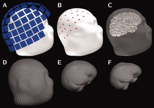
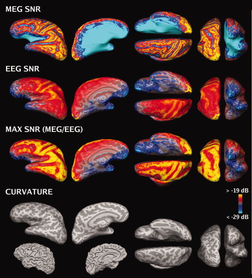
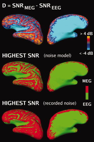
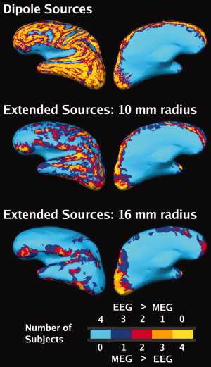
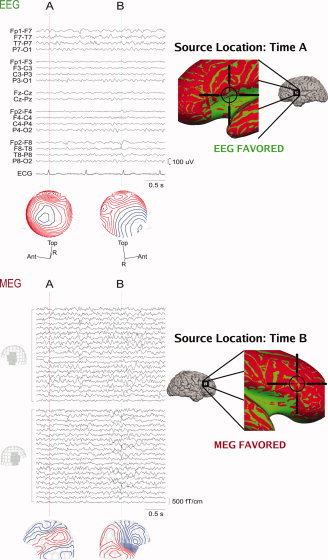
Although magnetoencephalography (MEG) and electroencephalography (EEG) have been available for decades, their relative merits are still debated. We examined regional differences in signal-to-noise-ratios (SNRs) of cortical sources in MEG and EEG. Data from four subjects were used to simulate focal and extended sources located on the cortical surface reconstructed from high-resolution magnetic resonance images. The SNR maps for MEG and EEG were found to be complementary. The SNR of deep sources was larger in EEG than in MEG, whereas the opposite was typically the case for superficial sources. Overall, the SNR maps were more uniform for EEG than for MEG. When using a noise model based on uniformly distributed random sources on the cortex, the SNR in MEG was found to be underestimated, compared with the maps obtained with noise estimated from actual recorded MEG and EEG data. With extended sources, the total area of cortex in which the SNR was higher in EEG than in MEG was larger than with focal sources. Clinically, SNR maps in a patient explained differential sensitivity of MEG and EEG in detecting epileptic activity. Our results emphasize the benefits of recording MEG and EEG simultaneously.


Figures

Figure 1
Figure 1
Sensor and surface configuration. A: The locations of the MEG sensor array with respect to the head (Subject 2). B: The locations of the EEG electrodes on the scalp. C: Surface rendering of the cerebral cortex with the scalp rendered semi‐transparent. The second row shows the tessellations of the scalp (D), the outer surface of the skull (E), and the inner surface of the skull (F) employed in the boundary‐element forward model. These surfaces were reconstructed from the structural MRI. [Color figure can be viewed in the online issue, which is available at www.interscience.wiley.com.]
Figure 2
Figure 2
SNR maps based on the noise model (group average, left hemisphere, plotted on Subject 2's brain). The color scale is identical in each SNR map. The SNR estimates plotted on the cortical surface: SNRMEG (first row), SNREEG (second row), maximum of SNRMEG and SNREEG (third row). Fourth row: inflated cortical curvature maps and folded cortex maps. Convex areas (gyri) and concave areas (sulcal walls) are indicated in light and dark gray, respectively.
Figure 3
Figure 3
Difference (D) SNR maps (group average, left hemisphere, plotted on the brain of Subject 2). Top row: Difference (D) maps based on the noise model. Middle row: D maps based on the noise model thresholded at D = 0. Red: D > 0 (MEG higher SNR), green: D < 0 (EEG higher SNR). The sulci, narrow crests of gyri, the insula and the medial surface of the cortex all indicate higher SNR in EEG, while other locations show higher SNR in MEG. Bottom row: D maps based on recorded noise thresholded at D = 0.
Figure 4
Figure 4
Effect of the extent of the source on SNR maps (noise model, group average, left hemisphere, plotted on subject 2's brain). Top row: Dipoles. Middle row: Extended patch sources, radius = 10 mm. Lower row: Extended patch sources, radius = 16 mm. The color code indicates at each location the number of subjects that have SNRMEG > SNREEG (i.e. D > 0). For example, areas colored yellow exhibited D > 0 in all four subjects at that location. The intermediate colors indicate locations with greater between‐subject variability.
Figure 5
Figure 5
MEG and EEG recording from an epileptic patient. Left, above: The EEG signals (standard clinical bipolar montage) and potential distributions at time instants A and B. Left, below: MEG signals in left and right frontotemporal planar gradiometers and the corresponding field distributions at times A and B. The spike at time A can be more easily detected from the EEG data whereas the spike at time B is more prominent in the MEG signals. Right: The locations of the spike sources at times A and B estimated with an equivalent current‐dipole model are superimposed on the difference SNR maps (green: SNREEG > SNRMEG, red: SNRMEG > SNREEG). Pial cortex maps are shown as well as expanded SNR maps in the region of the dipole source. The SNR maps correctly identify the modality that best represents the spikes at times A and B respectively.

References

    1. Ahonen AI,Hämäläinen MS,Ilmoniemi RJ,Kajola MJ,Knuutila JE,Simola JT,Vilkman VA( 1993): Sampling theory for neuromagnetic detector arrays. IEEE Trans Biomed Eng 40: 859–869. - PubMed
    1. Babiloni F,Babiloni C,Carducci F,Romani GL,Rossini PM,Angelone LM,Cincotti F( 2004): Multimodal integration of EEG and MEG data: a simulation study with variable signal‐to‐noise ratio and number of sensors. Hum Brain Mapp 22: 52–62. - PMC - PubMed
    1. Barkley GL,Baumgartner C( 2003): MEG and EEG in epilepsy. J Clin Neurophysiol 20: 163–178. - PubMed
    1. Baumgartner C( 2004): Controversies in clinical neurophysiology. MEG is superior to EEG in the localization of interictal epileptiform activity: Con. Clin Neurophysiol 115: 1010–1020. - PubMed
    1. Baumgartner C,Pataraia E,Lindinger G,Deecke L( 2000): Neuromagnetic recordings in temporal lobe epilepsy. J Clin Neurophysiol 17: 177–189. - PubMed

Publication types