. 2008 May 20;18(10):763-768.
doi: 10.1016/j.cub.2008.04.061.

Flexible representations of dynamics are used in object manipulation

Affiliations

Flexible representations of dynamics are used in object manipulation

Alaa A Ahmed et al. Curr Biol. .

Abstract

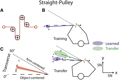
To manipulate an object skillfully, the brain must learn its dynamics, specifying the mapping between applied force and motion. A fundamental issue in sensorimotor control is whether such dynamics are represented in an extrinsic frame of reference tied to the object or an intrinsic frame of reference linked to the arm. Although previous studies have suggested that objects are represented in arm-centered coordinates [1-6], all of these studies have used objects with unusual and complex dynamics. Thus, it is not known how objects with natural dynamics are represented. Here we show that objects with simple (or familiar) dynamics and those with complex (or unfamiliar) dynamics are represented in object- and arm-centered coordinates, respectively. We also show that objects with simple dynamics are represented with an intermediate coordinate frame when vision of the object is removed. These results indicate that object dynamics can be flexibly represented in different coordinate frames by the brain. We suggest that with experience, the representation of the dynamics of a manipulated object may shift from a coordinate frame tied to the arm toward one that is linked to the object. The additional complexity required to represent dynamics in object-centered coordinates would be economical for familiar objects because such a representation allows object use regardless of the orientation of the object in hand.


Figures

Figure 1
Figure 1
Apparatus While seated, participants grasped two handles, each attached to a planar, force-generating, two-joint, robotic manipulandum. The arms were supported by low-friction air sleds (not shown), which restricted arm motion to the horizontal plane. Participants looked down onto a horizontal semisilvered mirror, located above the hands, that displayed circles representing their hand positions in the plane of arm movement. In the straight-visible condition, participants also viewed an elastic band directly attached to the two handles (as shown in the figure), and in the pulley condition, they viewed an elastic band wrapped around a visible, rotating pulley (see Figure 2).
Figure 2
Figure 2
Force Vectors The cartoons depict the arm configurations in the training and transfer positions for all six combinations of object condition (columns) and arm configuration (top and bottom panels). Participants stretched an elastic band (red lines) to a nearby target (black circles) with their right hand. Each blue cross represents the median force vector generated by a given participant during catch trials after learning. The thick blue lines show mean force vectors, averaged across participants, and the blue ellipses represent the corresponding 50% confidence ellipses. Each green cross represents the median force vector during transfer trials after learning in the training position. The thick green lines show mean force vectors, averaged across participants, and the green ellipses represent the corresponding 50% confidence ellipses. The predicted force-vector directions based on transfer in object- and arm-centered coordinates are represented by the dashed and dotted lines, respectively.
Figure 3
Figure 3
Left-Hand Movement The lines represent mean peak left-hand displacement in the training and transfer positions, averaged across participants, as a function of trial batch. The shaded areas depict ± 1 standard error (SE). Each participant's score is based on the median of the standard trials per batch. Transverse and sagittal arm configurations are shown by thick and thin lines, respectively.
Figure 4
Figure 4
Transfer Angles (A) The transfer angles for all object conditions and arm configurations are presented as normalized vectors in polar coordinates. For clarity, the vectors for the object conditions are scaled differently. Each cross represents the median transfer angle for a single participant, and the thick lines show mean angles averaged across participants. The shaded areas represent ± 1 SE. Object-centered and arm-centered predictions are represented by dashed and dotted lines, respectively. (B) The magnitude of the average transfer angle (±1 SE) for each object-condition is presented. Transverse and sagittal arm configurations are shown in purple and cyan, respectively.
Figure 5
Figure 5
Straight-Pulley Condition (A) Locations of the hands (red circles) and four pulleys used in the straight-pulley condition. (B) Each blue cross represents the median force vector generated by a given participant during catch trials after learning. The thick blue lines show mean force vectors, averaged across participants, and the blue ellipses represent the corresponding 50% confidence ellipses. Each green cross represents the median force vector during transfer trials after learning in the training position. The thick green line shows the mean force vector, averaged across participants, and the green ellipse represents the corresponding 50% confidence ellipse. (C) Each red cross represents the median transfer angle for a single participant, and the thick red line shows mean angles averaged across participants. The shaded areas represent ± 1 SE. Object-centered and arm-centered predictions are represented by dashed and dotted lines, respectively.

References

    1. Shadmehr R., Mussa-Ivaldi F.A. Adaptive representation of dynamics during learning of a motor task. J. Neurosci. 1994;14:3208–3224. - PMC - PubMed
    1. Shadmehr R., Moussavi Z.M. Spatial generalization from learning dynamics of reaching movements. J. Neurosci. 2000;20:7807–7815. - PMC - PubMed
    1. Malfait N., Shiller D.M., Ostry D.J. Transfer of motor learning across arm configurations. J. Neurosci. 2002;22:9656–9660. - PMC - PubMed
    1. Mah C.D., Mussa-Ivaldi F.A. Generalization of object manipulation skills learned without limb motion. J. Neurosci. 2003;23:4821–4825. - PMC - PubMed
    1. Bays P.M., Wolpert D.M. Actions and consequences in bimanual interaction are represented in different coordinate systems. J. Neurosci. 2006;26:7121–7126. - PMC - PubMed

Publication types

LinkOut - more resources