. 2008 May 27;105(21):7434-8.
doi: 10.1073/pnas.0712398105. Epub 2008 May 21.

Hydrodynamic metamaterials: microfabricated arrays to steer, refract, and focus streams of biomaterials

Affiliations

Hydrodynamic metamaterials: microfabricated arrays to steer, refract, and focus streams of biomaterials

Keith J Morton et al. Proc Natl Acad Sci U S A. .

Abstract

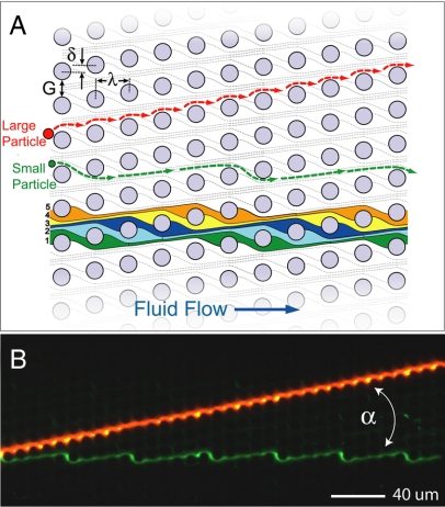
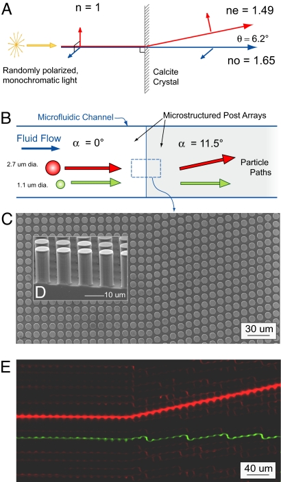
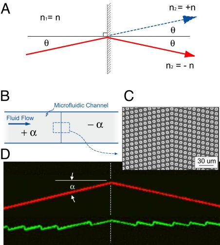
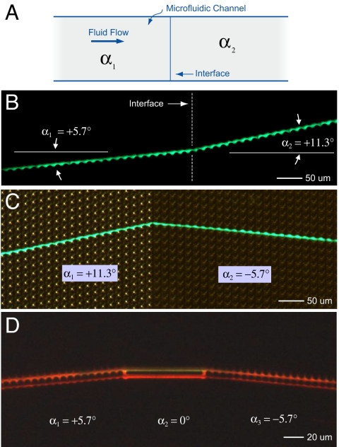
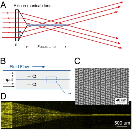
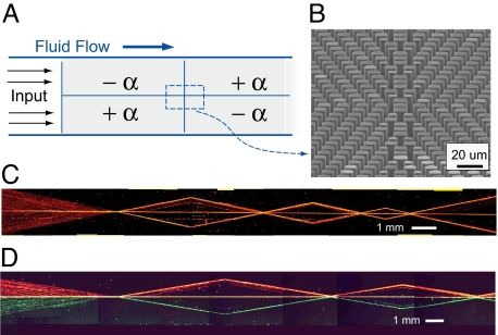
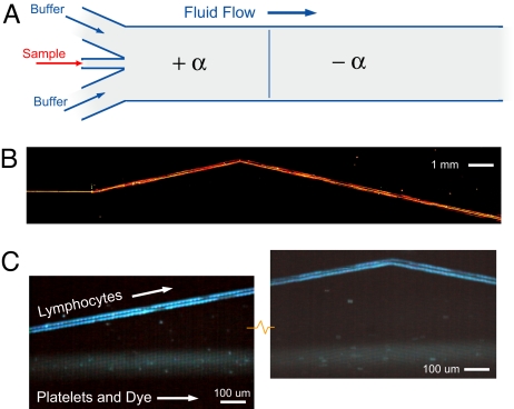
We show that it is possible to direct particles entrained in a fluid along trajectories much like rays of light in classical optics. A microstructured, asymmetric post array forms the core hydrodynamic element and is used as a building block to construct microfluidic metamaterials and to demonstrate refractive, focusing, and dispersive pathways for flowing beads and cells. The core element is based on the concept of deterministic lateral displacement where particles choose different paths through the asymmetric array based on their size: Particles larger than a critical size are displaced laterally at each row by a post and move along the asymmetric axis at an angle to the flow, while smaller particles move along streamline paths. We create compound elements with complex particle handling modes by tiling this core element using multiple transformation operations; we show that particle trajectories can be bent at an interface between two elements and that particles can be focused into hydrodynamic jets by using a single inlet port. Although particles propagate through these elements in a way that strongly resembles light rays propagating through optical elements, there are unique differences in the paths of our particles as compared with photons. The unusual aspects of these modular, microfluidic metamaterials form a rich design toolkit for mixing, separating, and analyzing cells and functional beads on-chip.


Conflict of interest statement

The authors declare no conflict of interest.

Figures

Fig. 1.
Fig. 1.
Size-based particle separation in an asymmetric array of posts. (A) Schematic of a deterministic lateral displacement (DLD) array showing definitions of the array parameters: The posts are periodically arranged with spacing λ; each downstream row is offset laterally from the previous row by the amount δ breaking the symmetry of the array. This array axis forms an angle α = tan−1(δ/λ) = tan−1(ε) with respect to the channel walls and therefore the direction of fluid flow. Because of the array asymmetry, fluid flow in the gaps between the posts G is partitioned into 1/ε slots delineated with individual colors. Each of these slots repeats every 1/ε rows so the flow through the array is on average straight. Particles transiting the gap near a post can be displaced into an adjacent streamline (from slot 1 to slot 2) if the particles radius is larger than the slot width in the gap. Therefore, larger particles (red) are deterministically displaced at each post and migrate at an angle α to the flow. Smaller particles (green) simply follow the streamline paths and flow through the array. (B) Separation of 2.7-μm red fluorescent beads and 1.0-μm green fluorescent beads by using the array (α = 11.3°, G = 4 μm, λ = 11 μm).
Fig. 2.
Fig. 2.
Optical and microfluidic birefringent interfaces. (A) Optical birefringence in a calcite crystal: normally incident, randomly polarized light, incident on the anisotropic crystal splits into two polarization dependent paths. Remarkably, the extraordinary ray, whose polarization is parallel to the calcite optical axis, is deflected away from the normal. (B) Schematic of particle trajectories at the interface between a neutral region and a microfluidic metamaterial element. Particles larger than a critical size follow the array asymmetry, whereas smaller particle follow the fluid flow. (C) The simplest metamaterial element is an asymmetric array of posts tilted at an angle +α relative to the channel walls and bulk fluid flow. Shown is a top-view scanning electron micrograph (SEM) of the interface between a neutral array (α = 0°) and an array with array angle α = 11.3° (the gap G = 4 μm and post pitch λ = 11 μm are the same for both sides). (D) Cross-sectional SEM image showing the microfabricated post array. (E) Equivalent microfluidic birefringence based on particle size showing the time-trace of a 2.7-μm red fluorescent transiting the interface and being deflected from the normal [see supporting information (SI) Movie S1]. Smaller, 1.1-μm red beads are not deflected at the interface; one such trace is highlighted in green to increase contrast.
Fig. 3.
Fig. 3.
Optical and microfluidic negative refraction. (A) Refraction of light at the interface between materials having same refractive index for both identical (blue, normal refraction) or opposite (red, negative refraction) signs. (B) Two birefringent microfluidic elements are connected in series form a prismatic metamaterial. The compound element is made by joining a +α array (upstream) to a −α array (downstream). (C) Top-view SEM of the interface between the two subelements. (D) False color, epifluorescent time exposure of a supercritical, 2.7-μm-diameter fluorescent particle (top trace, red) moving from the left to the right and refracting the boundary, and a subcritical, 1.0-μm particle (bottom trace, green) following the characteristic zigzag path across the interface (see Movie S2).
Fig. 4.
Fig. 4.
Particle steering using arrays with different angles. (A) Schematic of a microfluidic channel showing the interface between two elements with different array axis angles, α1 and α2. (B) Time trace of a single, 3.7-μm diameter fluorescent bead crossing an interface between two arrays having the same post pitch (λ = 20 μm) and spacing (G = 5 μm), but with different array angles. The bead initially moves along a trajectory α1 = +5.7° before crossing into an element where the array angle is larger (α2 = 11.3°) but still positive. (C) Time trace of a 3.7-μm bead moving from an array with a positive array angle (α1 = 11.3°) into an array with a shallower and negative angle (α2 = −5.7°). Here, in addition to the fluorescent image of the moving bead, an external directional lamp was used to illuminate the post array and highlight the difference between the upstream and downstream elements. (D) The interface between elements can also made such that particles travel straight for a predetermined distance. Here, a stream of 1.3-μm fluorescent beads first travels along an array angle of +5.7° (with λ = 8 μm and G = 2.0 μm), then transits entering a short horizontal section (in this case linking channels) before finally entering a third array element with angle −5.7°.
Fig. 5.
Fig. 5.
Optical and microfluidic focusing elements. (A) A conical lens or axicon focuses collimated incident light into a nominally nondiffracting line. (B) The microfluidic equivalent of a focusing lens is constructed by tiling a −α array and a +α array vertically. The focusing element +F directs incident particles to a line. (C) SEM image of the interface between the subelements. (D) Here, 2.7-μm diameter fluorescent particles enter the microfluidic device from a single inlet port and are rapidly focused within a few channel widths into a continuously flowing hydrodynamic jet.
Fig. 6.
Fig. 6.
Complex microfluidic metamaterial. (A) Schematic of a complex metamaterial constructed by tiling several focusing, defocusing, and refractive elements. (B) Tilted, cross-sectional SEM image showing the interface between four subelements. (C) Collage of time-exposure images showing particle motion through a series of different +F and −F elements; motion is from left to right with just a single inlet and single outlet port. (D) A similar device with two separate inputs allowing two differently colored bead streams in the top and bottom halves of the device. Observe that particle crossover between the two halves of the device is rare; particles only mix when hydrodynamically trapped along the center reflection axis.
Fig. 7.
Fig. 7.
Beam steering for cells and particles. (A) Schematic of a traditional, three-input design for creating a laminar-flow hydrodynamic jet in a channel. The first element in the channel is a simple birefringence medium followed downstream by longer element with the same characteristics but having the opposite angle. (B) Wide angle composite image showing steering of a jet of 2.7-μm-diameter beads streaming through two microfluidic metamaterial elements and refracting, and the interface between them. Note that in the second longer element, the bead path crosses over the original input position. (C Left) A similar device designed to bump blood lymphocytes, but not blood platelets, was used to demonstrate refraction of a stream of cells (α = 11.3°, G = 8 μm, λ = 11 μm). Depicted is time exposure showing the separation of lymphocytes, which track along the array axis, and platelets and residual labeling dye that follow the fluid flow direction. (C Right) Refraction of lymphocytes at the interface between +α and −α array elements (see Movie S3). The flow of the platelets and dye is undisturbed.

References

    1. Newton I. Walford, London: 1704. Opticks or a Treatise of the Reflections, Refractions, Inflections and Colours of Light.
    1. Squires TM, Quake SR. Microfluidics: Fluid physics at the nanoliter scale. Rev Mod Phys. 2005;77:977–1026.
    1. Atencia J, Beebe DJ. Controlled microfluidic interfaces. Nature. 2005;437:648–655. - PubMed
    1. Huang LR, Cox EC, Austin RH, Sturm JC. Continuous particle separation through deterministic lateral displacement. Science. 2004;304:987–990. - PubMed
    1. Saleh BEA, Teich MC. Fundamentals of Photonics. New York: Wiley; 1991.

Publication types

MeSH terms

LinkOut - more resources