Review
. 2008 Aug 17;60(11):1266-1277.
doi: 10.1016/j.addr.2008.03.017. Epub 2008 Apr 10.

Porous silicon in drug delivery devices and materials

Affiliations
Review

Porous silicon in drug delivery devices and materials

Emily J Anglin et al. Adv Drug Deliv Rev. .

Abstract

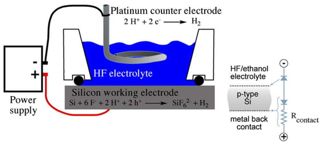
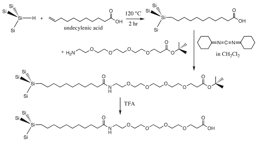
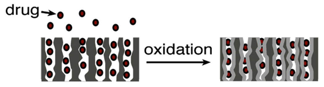
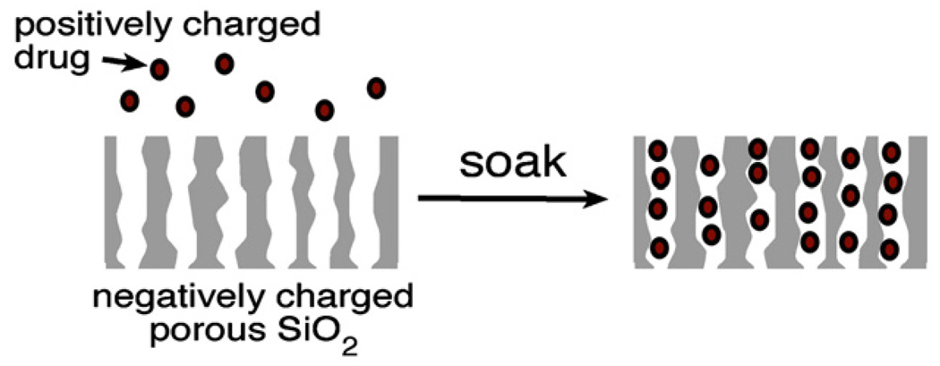
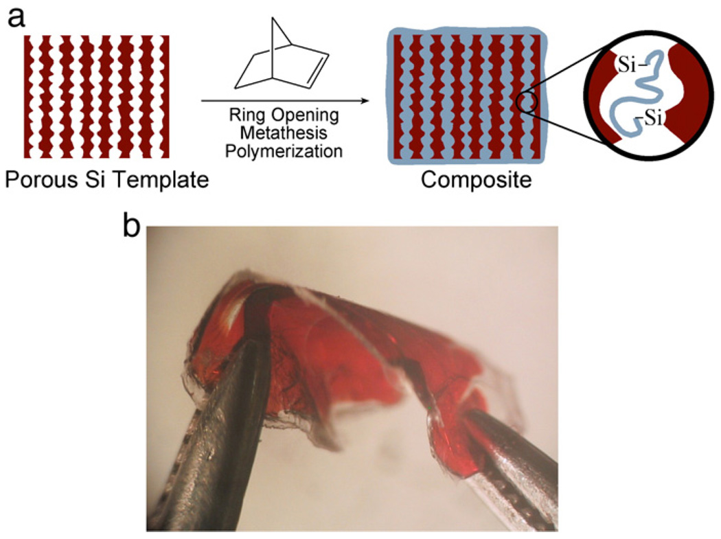
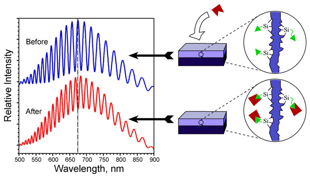
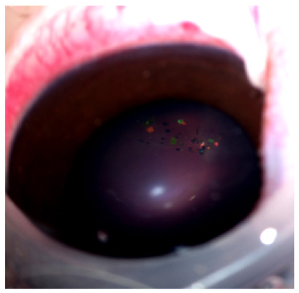
Porous Si exhibits a number of properties that make it an attractive material for controlled drug delivery applications: The electrochemical synthesis allows construction of tailored pore sizes and volumes that are controllable from the scale of microns to nanometers; a number of convenient chemistries exist for the modification of porous Si surfaces that can be used to control the amount, identity, and in vivo release rate of drug payloads and the resorption rate of the porous host matrix; the material can be used as a template for organic and biopolymers, to prepare composites with a designed nanostructure; and finally, the optical properties of photonic structures prepared from this material provide a self-reporting feature that can be monitored in vivo. This paper reviews the preparation, chemistry, and properties of electrochemically prepared porous Si or SiO2 hosts relevant to drug delivery applications.


Figures

Fig. 1
Fig. 1
Schematic of the etch cell used to prepare porous Si. The electrochemical half-reactions are shown, and the equivalent circuit for etching of a p-type Si wafer is shown at right.
Fig. 2
Fig. 2
Mechanism of Si oxidation during the formation of porous Si (adapted from reference [38]).
Fig. 3
Fig. 3
Adding a linker to porous Si via hydrosilylation. The short-chain PEG linker yields a hydrophilic surface that minimizes non-specific binding effects (adapted from reference [110]).
Fig. 4
Fig. 4
Building a bottle around a ship. A molecular or nanoparticle payload can be trapped by partial oxidation of the porous Si host layer. Oxidation produces a volume expansion (Si to SiO2) that shrinks the pores, locking the payload in place. After [124]
Fig. 5
Fig. 5
Trapping of a positively charged drug payload in a porous SiO2 layer by ionic adsorption. Porous SiO2 (oxidized porous Si) has a negative surface charge; molecules with positive charges will spontaneously adsorb to the inner pore walls and surface. This method is commonly used to load proteins [,,,–134]
Fig. 6
Fig. 6
Fabrication of a nanostructured composite from a porous Si template. A variety of solution- or melt-processible organic and biopolymers can be solution-cast or injection-molded into a porous Si or porous SiO2 host. The composite can be used as-formed, or the template can be removed by chemical dissolution. If the template is removed, the polymer castings often replicate the nanostructure of the master. Use of these castings as vapor sensors, deformable and tunable optical filters, and as self-reporting, bioresorbable materials has been demonstrated [146].
Fig. 7
Fig. 7
In-situ polymerization and crosslinking of a porous Si template. The catalyzed reaction generates a composite porous Si/polymer matrix in which the polymer is covalently attached to porous Si via Si–C bonds. The chemical and mechanical stability of the chemically crosslinked porous Si matrix is significantly improved relative to the porous Si film alone. After [152].
Fig. 8
Fig. 8
Schematic demonstrating the change in a reflectance spectrum from a single layer of porous Si upon introduction of a molecular species into the porous matrix. The change in refractive index of the composite film results in a red shift of the Fabry–Pérot interference fringes. The reverse process can also be monitored, yielding a blue shift in the spectrum.
Fig. 9
Fig. 9
Photograph of porous Si microparticles in a live rabbit eye. The particles were prepared as multilayered photonic crystals (rugate filters), and they appear as brightly colored flecks that can be seen floating the vitreous. The color of the microparticles shifts to the blue as the particles degrade in vivo, providing a predictive metric to the clinician.
Fig. 10
Fig. 10
Light microscope image of porous Si microparticles. These particles were prepared as multilayered photonic crystals (rugate filters) and display various spectral colors depending on the periodicity of their layered nanostructure. Nominal particle size is 50 µm.

Similar articles

Cited by

References

    1. Collins RT, Fauchet PM, Tischler MA. Porous silicon: from luminescence to LEDs. Phys. Today. 1997;50:24–31.
    1. Lazarouk S, Jaguiro P, Katsouba S, et al. Stable electroluminescence from reverse biased n-type porous silicon-aluminum Schottky junction device. Appl. Phys. Lett. 1996;68:2108–2110.
    1. Steiner P, Kozlowski F, Lang W. Light-emitting porous silicon diode with an increased electroluminescence quantum efficiency. Appl. Phys. Lett. 1993;62:2700–2702.
    1. Richter A, Steiner P, Kozlowski F, Lang W. Current-induced light emission from a porous Si device. IEEE Elec. Dev. Lett. 1991;12:691–692.
    1. Foucaran A, Pascal-Delannoy F, Giani A, Sackda A, Combette P, Boyer A. Porous silicon layers used for gas sensor applications. Thin Solid Films. 1997;297:317–320.

Publication types