

doi: 10.1038/nmeth.1217.
Laminar flow cells for single-molecule studies of DNA-protein interactions
Affiliations
- PMID: 18511919
- PMCID: PMC7141782
- DOI: 10.1038/nmeth.1217
Item in Clipboard
Laminar flow cells for single-molecule studies of DNA-protein interactions
Nat Methods.
2008 Jun.
Abstract
Microfluidic flow cells are used in single-molecule experiments, enabling measurements to be made with high spatial and temporal resolution. We discuss the fundamental processes affecting flow cell operation and describe the flow cells in use at present for studying the interaction of optically trapped or mechanically isolated, single DNA molecules with proteins. To assist the experimentalist in flow cell selection, we review the construction techniques and materials used to fabricate both single- and multiple-channel flow cells and the advantages of each design for different experiments.
Figures
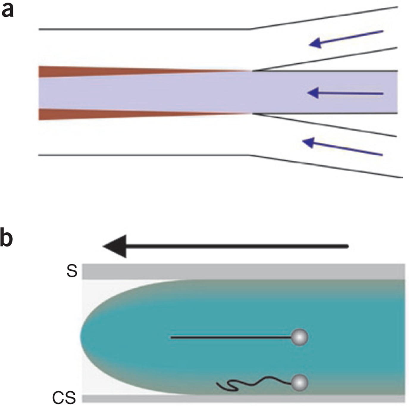
Fluid flow in multistream laminar flow cells. (a) Interchannel diffusion is the main source of mixing between adjacent fluid streams. The flow paths are indicated by blue arrows, and the individual streams are colored white, blue and white. The widening regions of transverse diffusion between channels are indicated in maroon. (b) The flow profile (green) in laminar flow cells is parabolic. The flow cell is viewed from the side with the direction of flow indicated by the black arrow. The fastest fluid velocities occur at the center of the flow cell, and the slowest occur next to the flow cell surfaces. The upper optically trapped DNA-bead complex is positioned ~18 μm from the surface, resulting in full extension of the DNA molecule (black string). Closer to the surface, DNA molecules are not fully stretched (lower DNA molecule). S, slide; CS, coverslip.

A simple single-stream flow cell. Two different versions of a single channel design are shown. The separate versions are constructed using either double-sided,, or acrylic tape (green) or Parafilm,, (violet), resulting in channels ranging in depth from 25 to 254 μm. For the tape versions, the open ends can be sealed with epoxy, or alternatively, the channel can be cut out of the tape in a manner identical to that shown for the Parafilm design. The entry and exit ports are then connected to tubing either directly (attached using epoxy to bond directly to the glass slide) or through connectors. The purple arrow indicates the flow direction.

A single-stream flow cell for force measurements. The flow cell is placed in a chamber holder (tan). Adapted from refs. ,. For clarity, the two Parafilm layers are shown as a single layer. One bead is held by the micropipette while the second is held in an optical trap (red, inset). Opposing ends of DNA molecules are attached to separate beads. 1, coverslip; 2, Parafilm layers; 3, microscope slide.
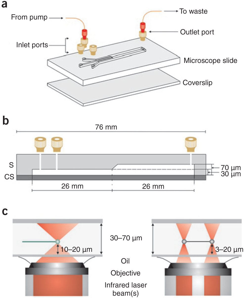
Multistream laminar flow cell for single-molecule studies. (a) A three-stream laminar flow cell constructed from glass. The designis for an inverted microscope. Inlet channel widths are 250 μm and the common channel width is 750 μm. Machined connectors (tan; Upchurch Scientific) are attached to the slide at the holes. These are then connected to Fingertight connectors (red; Upchurch Scientific) to facilitate the attachment of PEEK tubing. Identical methods may be used to construct two-channel flow cells,. (A fully assembled flow cell positioned on a microscope stage is shown in Supplementary Fig. 1a.) (b) A side view of the flow cell in a showing relevant dimensions. (c) A side view of the flow cell demonstrating the trapping height from the coverslip using either one (left) or two (right) optical traps. Optical trapping and DNA visualization are carried out in the deeper portion of the flow cell in our groups.
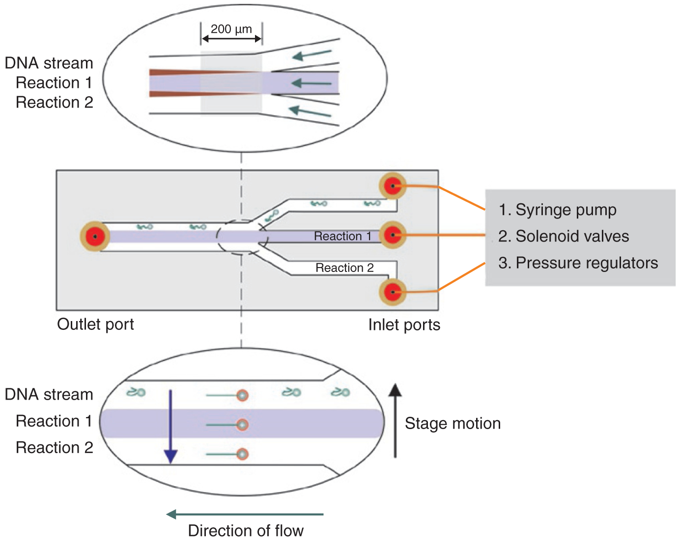
Multistream flow cells facilitate careful single-molecule experiments. A three-channel flow cell, viewed from the top, can be connected to a syringe pump, solenoid valves (Clippard Europe) or pressure regulators to introduce buffers. The fluid stream in the middle channel is colored blue for clarity. DNA-bead complexes are introduced into the first channel, where they are optically trapped. Upper inset: the optical trap is positioned in the area (gray shaded box) within 200 μm of the flow junction, where transverse diffusion leading to mixing (maroon) is minimized (see Box 2). The flow paths are indicated by green arrows. Lower inset: an optically trapped DNA-bead complex is translated (blue arrow), perpendicular to the flow, from the DNA stream to the two reaction streams. Translation is facilitated by microscope stage motion (black arrow).
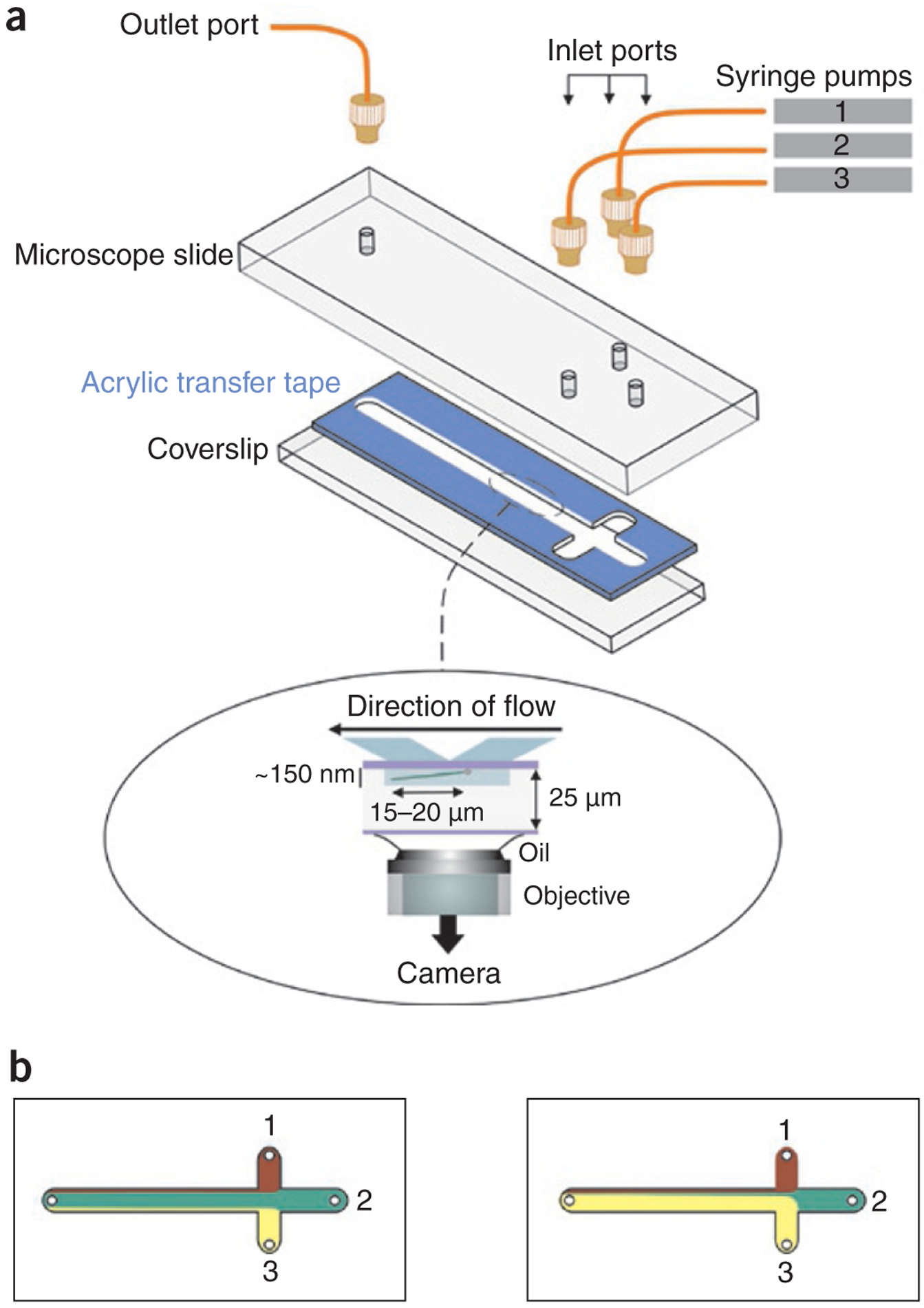
A laminar boundary-steering flow cell for TIRFM. (a) The flow cell design and assembly. The width of all channels is 3 mm. Nanoport connectors (tan) are used to secure PEEK tubing to the flow cell. Inset, side view of flow cell being used for TIRFM. A single DNA molecule (green) attached to the surface through streptavidin (sphere) is shown stretched by the constant flow. The DNA is visible within the evanescent wave (~150 nm depth; gray rectangle). (b) Laminar flow boundaries are steered by altering flow rates of individual pumps while maintaining the net flow rate constant. The numbers indicate the three syringe pumps used to control flow. The colors indicate different buffer solutions. Left, the dominant pump is syringe pump 2; right, the dominant pump is pump 3. Panel b adapted from ref. .
References
-
- Bianco PR et al. Processive translocation and DNA unwinding by individual RecBCD enzyme molecules. Nature 409, 374–378 (2001). - PubMed
-
- Handa N, Bianco PR, Baskin RJ & Kowalczykowski S Direct visualization of RecBCD movement reveals cotranslocation of the RecD motor after χ recognition. Mol. Cell 17, 745–750 (2005). - PubMed
-
- Spies M et al. A molecular throttle: the recombination hotspot chi controls DNA translocation by the RecBCD helicase. Cell 114, 647–654 (2003). - PubMed
-
- Chemla YR et al. Mechanism of force generation of a viral DNA packaging motor. Cell 122, 683–692 (2005). - PubMed
Publication types
MeSH terms
Substances
Grants and funding
LinkOut - more resources
Full Text Sources
Other Literature Sources
