. 2008 Aug;193(2):274-85.
doi: 10.1016/j.jmr.2008.05.016. Epub 2008 May 24.

An open-access, very-low-field MRI system for posture-dependent 3He human lung imaging

Affiliations

An open-access, very-low-field MRI system for posture-dependent 3He human lung imaging

L L Tsai et al. J Magn Reson. 2008 Aug.

Abstract

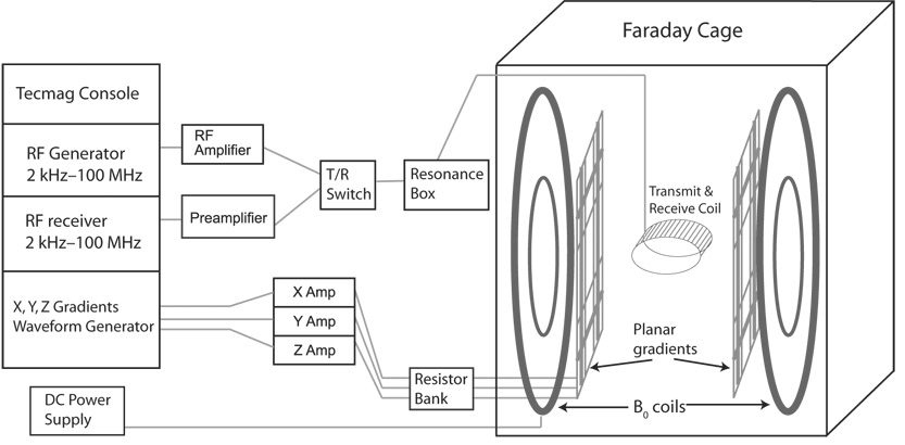
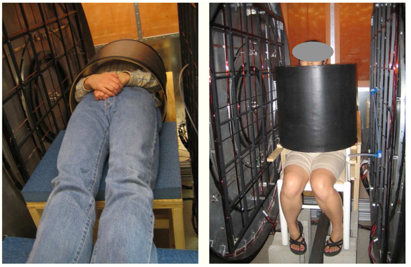
We describe the design and operation of an open-access, very-low-field, magnetic resonance imaging (MRI) system for in vivo hyperpolarized 3He imaging of the human lungs. This system permits the study of lung function in both horizontal and upright postures, a capability with important implications in pulmonary physiology and clinical medicine, including asthma and obesity. The imager uses a bi-planar B(0) coil design that produces an optimized 65 G (6.5 mT) magnetic field for 3He MRI at 210 kHz. Three sets of bi-planar coils produce the x, y, and z magnetic field gradients while providing a 79-cm inter-coil gap for the imaging subject. We use solenoidal Q-spoiled RF coils for operation at low frequencies, and are able to exploit insignificant sample loading to allow for pre-tuning/matching schemes and for accurate pre-calibration of flip angles. We obtain sufficient SNR to acquire 2D 3He images with up to 2.8mm resolution, and present initial 2D and 3D 3He images of human lungs in both supine and upright orientations. 1H MRI can also be performed for diagnostic and calibration reasons.


Figures

Fig. 1
Fig. 1
Schematic of the open-access human MRI system. The major components include an MRI research console (left), electronics components for RF and gradient pulse generation and B0 control (center), and the B0, gradient and B1 coils, located inside an RF-shielding Faraday cage (right). The resonance box, T/R switch and preamplifier are located inside the Faraday cage, but are drawn as shown for clarity.
Fig. 2
Fig. 2
Left: The B0 and gradient coils mounted on the aluminum flange. The arrows point to the outer and inner B0 coils. The other circular coils are the z gradient coils, while the rectangular coils are the x and y gradient coils. Right: A view of the imaging region with the imaging axes defined. The x axis points out of the page.
Fig. 3
Fig. 3
Calculated plot of B0 homogeneity for the biplanar, four-coil arrangement. The ordinate represents the y axis of the imager and intersects the center of the magnet at zero. The abscissa represents the distance from the central y axis, along z; thus, one half of the region of interest is shown. Each contour line is a 25 ppm Bz deviation from the center B0. The design target DSV is 0.4 m.
Fig. 4
Fig. 4
B0 field map for the x-z plane, obtained after optimization of passive shim placement. Contours indicate deviation of 1H NMR frequency in Hz from the zero–center frequency is 210 kHz. Across a human lung of width ~ 25 cm, ν0 ~ ± 80 Hz, which implies the B0 homogeneity ΔB0 ~ ± 0.02 G or about 350 ppm.
Fig. 5
Fig. 5
Sample output of the MATLAB gradient coil optimization routine, in this case for a z gradient coil form. The program determines the magnetic field strength and produces a predicted gradient field map as well as plots of the deviation from an ideal gradient for the given coil design under consideration.
Fig. 6
Fig. 6
Left: A diagram of the z gradient loop pattern, showing the inner, middle, and outer sections. The current flow is in the same direction for all loops. Right: A diagram of the y gradient loop pattern, with thicker lines indicating more turns. The current flow is in the same direction for all loops. The loop dimensions for the y gradient pattern are denoted by letters on the figure: A = 8.05 cm, B = 24.75 cm, C = 45.9, 46.4, and 46.9 cm, D = 68.0, 68.5, 69.0, 69.5 and 70.0 cm. For the x gradient pattern, the corresponding dimensions are: A = 8.55 cm, B = 26.4 cm, C = 47.5, 48.0, and 48.5 cm, D = 68.0, 68.5, 69.0, 69.5 and 70.0 cm
Fig. 7
Fig. 7
Measured 3He flip-angle versus position along the center axis of the human chest coil oriented for supine lung imaging (i.e., along the imager’s x axis). Flip-angle calibrations were performed on hyperpolarized 3He cell #402 which had a 3 cm width along the x axis. Displacement is measured from one end of the chest coil. The solid curve is a fit of the data to the function describing the B1 field created by an ideal finite solenoid.
Fig. 8
Fig. 8
Measured SWR as a function of frequency for the human chest coil unloaded as well as loaded by two different human subjects weighing between 60–80 kg.
Fig. 9
Fig. 9
The OAI with human subjects in the supine position (left) and the upright position (right).
Fig. 10
Fig. 10
Demonstration of human lung imaging with the open-access imager. All images shown here are from the same subject. Left: 2D projection 3He MR image with the subject supine. From [31]. Center: 2D projection 3He MR image with the subject vertical. From [31]. Right: 3D reconstructed 3He MR image with the subject supine. The anterior face of the lungs is shown in all images, revealing the cardiac profile. Imaging parameters: B0 = 65 G, ν0 = 210 kHz, FOV = 50 cm, no signal averaging, θ = 4.1°, TR = 86 ms, TE = 29 ms. For 2D images, dataset was 128 × 64, zero-filled to 128 × 128, total scan time ~ 4 s. For the 3D image, dataset was 128 × 64 × 6, zero-filled to 128 × 128 × 8, slice thickness = 1.5 cm, total scan time ~ 33 s.

References

    1. Walker TG, Happer W. Spin-exchange optical pumping of noble-gas nuclei. Rev. Mod. Phys. 1997;69(2):629–642.
    1. Nacher P-J, Leduc M. Optical-Pumping in 3He with a Laser. J. de Phys. 1985;46(12):2057–2073.
    1. Leawoods JC, Yablonskiy DA, Saam BT, Gierada DS, Conradi MS. Hyperpolarized He-3 gas production and MR imaging of the lung. Concepts Magn. Reson. 2001;13(5):277–293.
    1. Moller HE, Chen XJ, Saam B, Hagspiel KD, Johnson GA, Altes TA, de Lange EE, Kauczor HU. MRI of the lungs using hyperpolarized noble gases. Magn. Reson. Med. 2002;47(6):1029–1051. - PubMed
    1. Salerno M, Altes TA, Brookeman JR, de Lange EE, Mugler JP., III Dynamic spiral MRI of pulmonary gas flow using hyperpolarized 3He: preliminary studies in healthy and diseased lungs. Magn. Reson. Med. 2001;46(4):667–677. - PubMed

Publication types