

Geometric calibration of a mobile C-arm for intraoperative cone-beam CT
- PMID: 18561688
- PMCID: PMC2809734
- DOI: 10.1118/1.2907563
Geometric calibration of a mobile C-arm for intraoperative cone-beam CT
Abstract
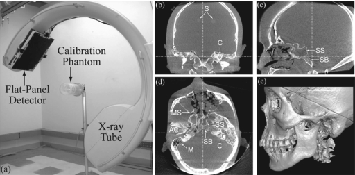
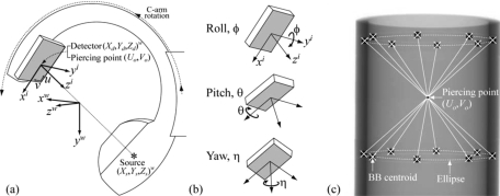
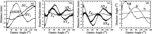
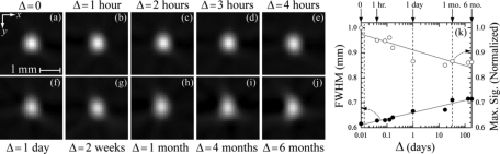
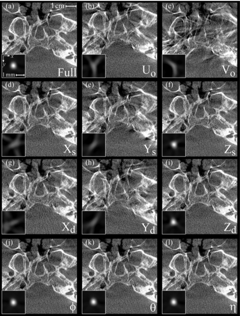
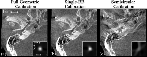
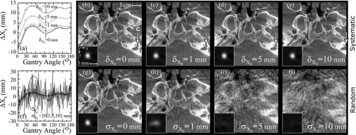
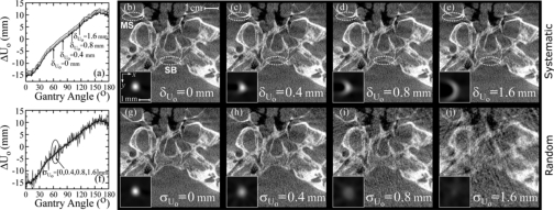
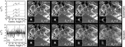
A geometric calibration method that determines a complete description of source-detector geometry was adapted to a mobile C-arm for cone-beam computed tomography (CBCT). The non-iterative calibration algorithm calculates a unique solution for the positions of the source (X(s), Y(s), Z(s)), detector (X(d), Y(d), Z(d)), piercing point (U(o), V(o)), and detector rotation angles (phi, theta, eta) based on projections of a phantom consisting of two plane-parallel circles of ball bearings encased in a cylindrical acrylic tube. The prototype C-arm system was based on a Siemens PowerMobil modified to provide flat-panel CBCT for image-guided interventions. The magnitude of geometric nonidealities in the source-detector orbit was measured, and the short-term (approximately 4 h) and long-term (approximately 6 months) reproducibility of the calibration was evaluated. The C-arm exhibits large geometric nonidealities due to mechanical flex, with maximum departures from the average semicircular orbit of deltaU(o) = 15.8 mm and deltaV(o) = 9.8 mm (for the piercing point), deltaX and deltaY = 6-8 mm and deltaZ = 1 mm (for the source and detector), and deltaphi approximately 2.9 degrees, deltatheta approximately 1.9 degrees, and delta eta approximately 0.8 degrees (for the detector tilt/rotation). Despite such significant departures from a semicircular orbit, these system parameters were found to be reproducible, and therefore correctable by geometric calibration. Short-term reproducibility was < 0.16 mm (subpixel) for the piercing point coordinates, < 0.25 mm for the source-detector X and Y, < 0.035 mm for the source-detector Z, and < 0.02 degrees for the detector angles. Long-term reproducibility was similarly high, demonstrated by image quality and spatial resolution measurements over a period of 6 months. For example, the full-width at half-maximum (FWHM) in axial images of a thin steel wire increased slightly as a function of the time (delta) between calibration and image acquisition: FWHM=0.62, 0.63, 0.66, 0.71, and 0.72 mm at delta = 0 s, 1 h, 1 day, 1 month, and 6 months, respectively. For ongoing clinical trials in CBCT-guided surgery at our institution, geometric calibration is conducted monthly to provide sufficient three-dimensional (3D) image quality while managing time and workflow considerations of the calibration and quality assurance process. The sensitivity of 3D image quality to each of the system parameters was investigated, as was the tolerance to systematic and random errors in the geometric parameters, showing the most sensitive parameters to be the piercing point coordinates (U(o), V(o)) and in-plane positions of the source (X(s), Y(s)) and detector (X(d), Y(d)). Errors in the out-of-plane position of the source (Z(s)) and detector (Z(d)) and the detector angles (phi, theta, eta) were shown to have subtler effects on 3D image quality.
Figures
Similar articles
-
Accurate technique for complete geometric calibration of cone-beam computed tomography systems.Med Phys. 2005 Apr;32(4):968-83. doi: 10.1118/1.1869652. Med Phys. 2005. PMID: 15895580
-
Auto calibration of a cone-beam-CT.Med Phys. 2012 Oct;39(10):5959-70. doi: 10.1118/1.4739247. Med Phys. 2012. PMID: 23039634
-
A mobile isocentric C-arm for intraoperative cone-beam CT: Technical assessment of dose and 3D imaging performance.Med Phys. 2020 Mar;47(3):958-974. doi: 10.1002/mp.13983. Epub 2020 Jan 6. Med Phys. 2020. PMID: 31863480 Free PMC article.
-
AAPM Task Group Report 238: 3D C-arms with volumetric imaging capability.Med Phys. 2023 Aug;50(8):e904-e945. doi: 10.1002/mp.16245. Epub 2023 Feb 20. Med Phys. 2023. PMID: 36710257 Free PMC article. Review.
-
Source-detector trajectory optimization in cone-beam computed tomography: a comprehensive review on today's state-of-the-art.Phys Med Biol. 2022 Aug 16;67(16). doi: 10.1088/1361-6560/ac8590. Phys Med Biol. 2022. PMID: 35905731 Review.
Cited by
-
Automatic image-to-world registration based on x-ray projections in cone-beam CT-guided interventions.Med Phys. 2009 May;36(5):1800-12. doi: 10.1118/1.3117609. Med Phys. 2009. PMID: 19544799 Free PMC article.
-
Image quality and dose characteristics for an O-arm intraoperative imaging system with model-based image reconstruction.Med Phys. 2018 Nov;45(11):4857-4868. doi: 10.1002/mp.13167. Epub 2018 Oct 9. Med Phys. 2018. PMID: 30180274 Free PMC article.
-
Self-calibration of cone-beam CT geometry using 3D-2D image registration.Phys Med Biol. 2016 Apr 7;61(7):2613-32. doi: 10.1088/0031-9155/61/7/2613. Epub 2016 Mar 10. Phys Med Biol. 2016. PMID: 26961687 Free PMC article.
-
An active contour method for bone cement reconstruction from C-arm x-ray images.IEEE Trans Med Imaging. 2012 Apr;31(4):860-9. doi: 10.1109/TMI.2011.2171498. Epub 2011 Oct 13. IEEE Trans Med Imaging. 2012. PMID: 21997251 Free PMC article.
-
An Automatic 3-D Reconstruction of Coronary Arteries by Stereopsis.J Med Syst. 2016 Apr;40(4):94. doi: 10.1007/s10916-016-0455-z. Epub 2016 Feb 10. J Med Syst. 2016. PMID: 26860917
References
-
- Siewerdsen J. H., Jaffray D. A., Edmundson G. K., Sanders W. P., Wong J. W., and Martinez A., “Flat-panel cone-beam CT: A novel imaging technology for image-guided procedures,” Proc. SPIE PSISDG10.1117/12.428085 4319, 435–444 (2001). - DOI
Publication types
MeSH terms
Grants and funding
LinkOut - more resources
Full Text Sources
Other Literature Sources
