. 2008 Aug 1;71(5):1591-9.
doi: 10.1016/j.ijrobp.2008.04.025.

High-resolution, small animal radiation research platform with x-ray tomographic guidance capabilities

Affiliations

High-resolution, small animal radiation research platform with x-ray tomographic guidance capabilities

John Wong et al. Int J Radiat Oncol Biol Phys. .

Abstract

Purpose: To demonstrate the computed tomography, conformal irradiation, and treatment planning capabilities of a small animal radiation research platform (SARRP).

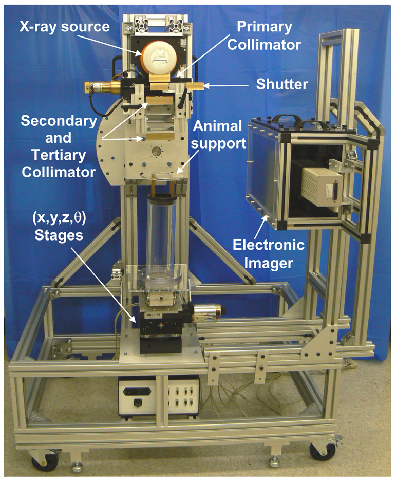
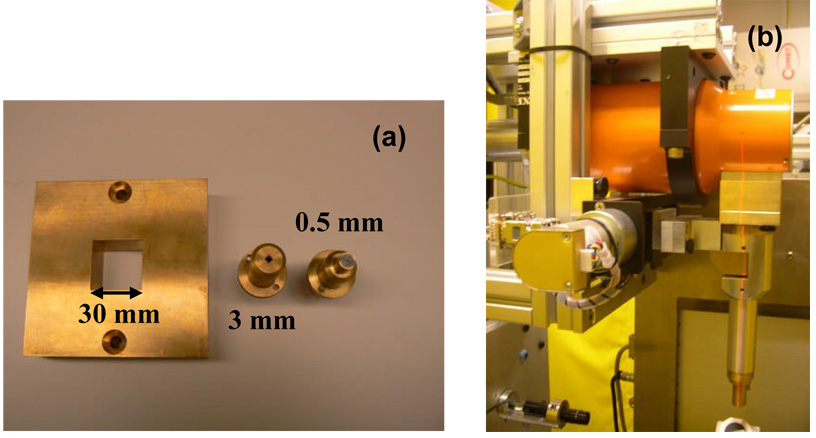
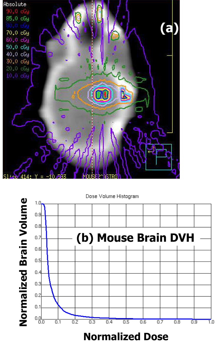
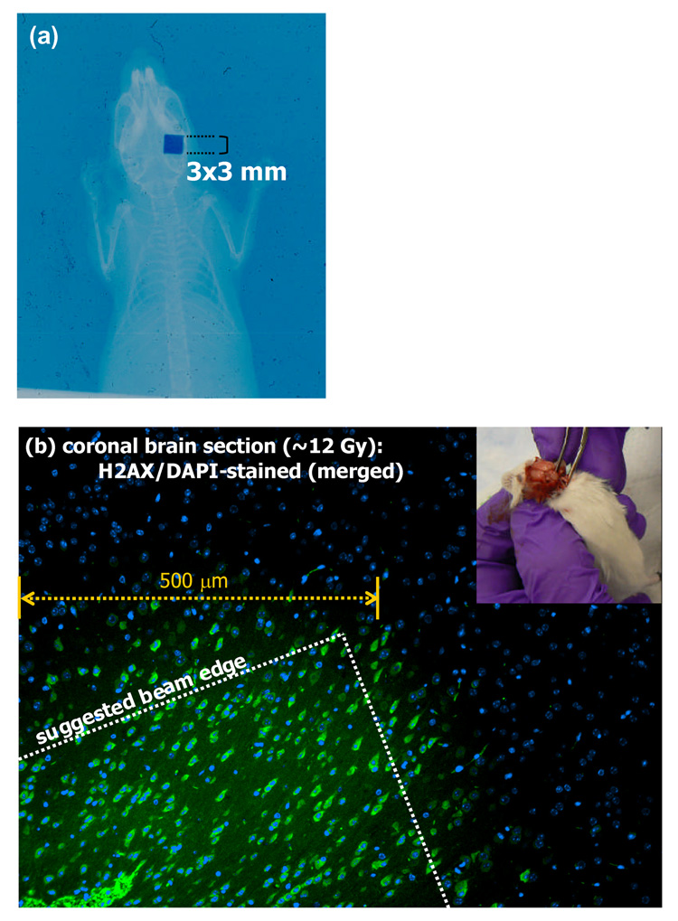
Methods and materials: The SARRP uses a dual-focal spot, constant voltage X-ray source mounted on a gantry with a source-to-isocenter distance of 35 cm. Gantry rotation is limited to 120 degrees from vertical. X-rays of 80-100 kVp from the smaller 0.4-mm focal spot are used for imaging. Both 0.4-mm and 3.0-mm focal spots operate at 225 kVp for irradiation. Robotic translate/rotate stages are used to position the animal. Cone-beam computed tomography is achieved by rotating the horizontal animal between the stationary X-ray source and a flat-panel detector. The radiation beams range from 0.5 mm in diameter to 60 x 60 mm(2). Dosimetry is measured with radiochromic films. Monte Carlo dose calculations are used for treatment planning. The combination of gantry and robotic stage motions facilitate conformal irradiation.

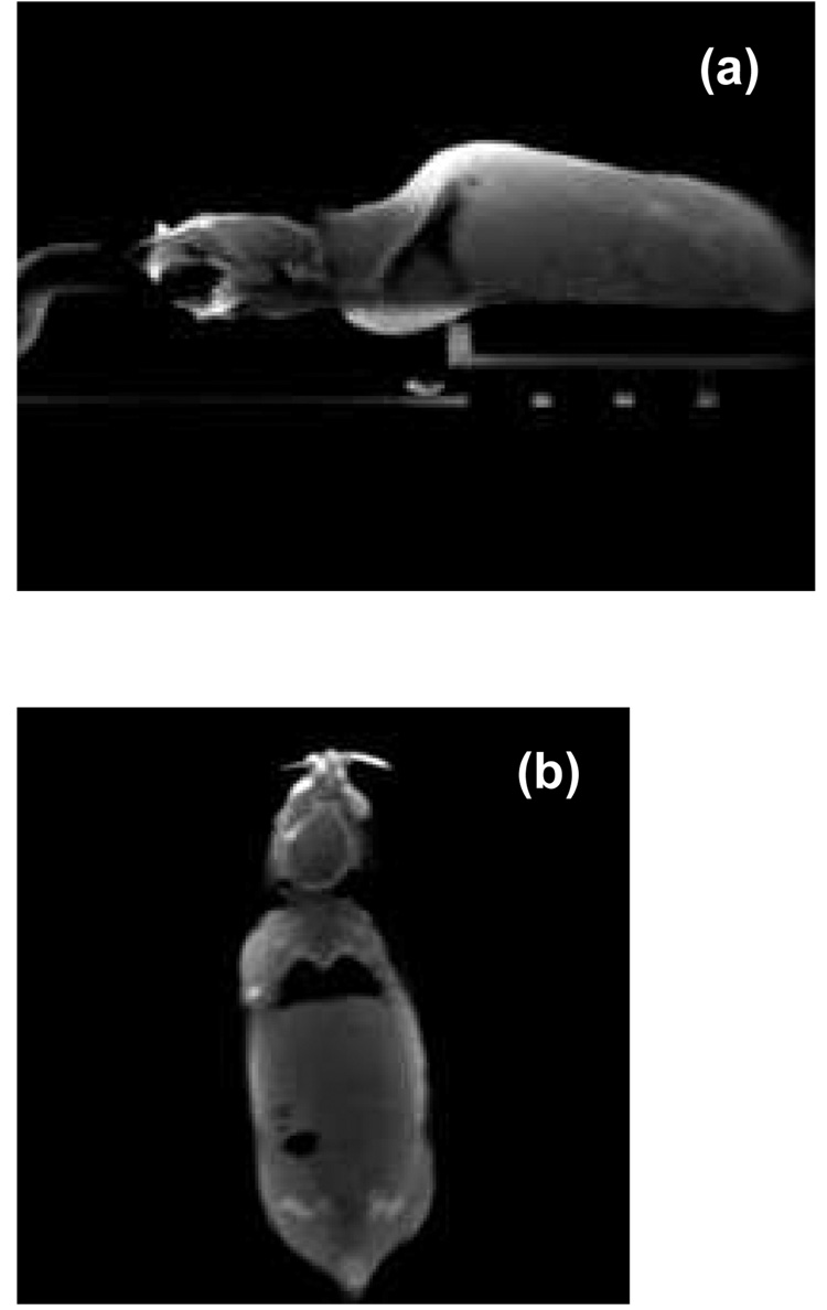
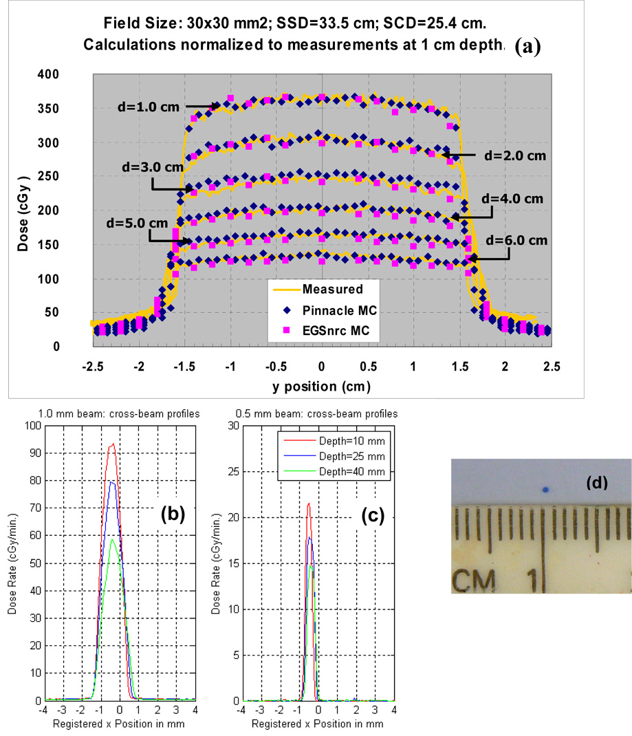
Results: The SARRP spans 3 ft x 4 ft x 6 ft (width x length x height). Depending on the filtration, the isocenter dose outputs at a 1-cm depth in water were 22-375 cGy/min from the smallest to the largest radiation fields. The 20-80% dose falloff spanned 0.16 mm. Cone-beam computed tomography with 0.6 x 0.6 x 0.6 mm(3) voxel resolution was acquired with a dose of <1 cGy. Treatment planning was performed at submillimeter resolution.

Conclusion: The capability of the SARRP to deliver highly focal beams to multiple animal model systems provides new research opportunities that more realistically bridge laboratory research and clinical translation.


Conflict of interest statement

Statement of Conflict of Interest

There are no conflicts of interest to be reported for all listed authors.

Figures

Figure 1
Figure 1
A picture of the small animal radiation research platform (SARRP) with conformal irradiation and cone beam CT guidance capabilities. The maximum extent of the system measures 3 ft in width, 4 ft in length, and 6 ft in height. It is equipped with wheels for ease of transport, but rests on stops for stationary use. The camera-based electronic imaging system has since been replaced with a 21cm × 21 cm flat panel amorphous silicon detector, 9 months prior to this writing.
Figure 2
Figure 2
(a) A picture of the tertiary brass collimation inserts with dimensions of 30 mm × 30 mm, 3 mm × 3mm and 0.5 mm diameter for the SARRP. (b) A picture of the radiosurgery-like collimating cone assembly attached to primary collimator of the SARRP for small field irradiations (< 5mm × 5mm in dimensions).
Figure 3
Figure 3
A CAD drawing of the novel configuration for cone-beam CT imaging on the SARRP. The x-ray source and a flat panel amorphous silicon detector are fixed at opposite horizontal positions of 90° and 270° respectively. The animal subject is rotated by the robotic stage. The 21 cm × 21 cm flat panel amorphous silicon detector has replaced the camera-based electronic imaging system of Figure 1.
Figure 4
Figure 4
A surface-rendered display of the Pinnacle3 3D treatment planning system showing the irradiation of a mouse brain using 15 beams equally spaced in a coronal arc arrangement. Each beam is of 1 mm in diameter.
Figure 5
Figure 5
(a) A sagittal slice of cone-beam CT of an anesthetized mouse scanned in the prone position. (b) A coronal CBCT slice of the same mouse. The mouse was immobilized with a custom head holder equipped with ear-pins and bite-block. The projection images were acquired with the flat panel detector.
Figure 6
Figure 6
(a) Measured cross-beam profiles at depths in plastic water for a 30 mm × 30 mm beam at a SSD of 33.5 cm, in comparison with the Monte Carlo calculations by the Pinnacle3 research (blue) and EGSnrc (pink) codes respectively. The added filtration was 4 mm Al. (b) and (c) Measured cross-beam profiles for the smallest beams of 1 mm and 0.5 mm diameters formed by “nozzle” collimators, respectively. The added filtrations were 0.5 mm Cu. Note that the beams are shifted from the expected central axis beam path by about 0.5mm. A picture of one of the exposed EBT film is shown in (d).
Figure 7
Figure 7
(a) The EGSnrc generated isodose distributions overlaid on a coronal CT slice of one of the mouse brains irradiated by the fifteen 1 mm diameter beams arrangement as shown in Figure 4. The “dose in air” artifacts are due to non-zero density CT numbers in the calculation grid. The added filtration was 4 mm Al. (b) The corresponding dose volume histogram of the irradiated mouse brain, contoured as the soft tissue density volume encased by the skull.
Figure 8
Figure 8
(a) A double-exposed EBT film of the mouse irradiation where a single 3 mm × 3mm beam was directed posteriorily to the right hemisphere. (b) A merged image of the sectioned mouse brain that was stained with DAPI for cell nuclei and with antibody against γ-H2AX for correspondence with radiation-induced DNA strand breaks. The entire section shows DAPI staining, while there is an apparent sharp demarcation of a region that also shows γ-H2AX staining. A beam edge is suggested on the image as the experiment did not include geometric validation of the coincidence of the irradiation and γ-H2AX regions. The inset in the figure shows the extraction of the irradiated mouse brain for staining.

References

    1. Wong J, Armour E, Oldham M, et al. An Image Guided Small Animal Radiation Research Platform. Proceedings of European Society for Therapeutic Radiology and Oncology (ESTRO 21) Praha, Rad. Oncol. 2002;64(S1):S61.
    1. DesRosiers C, Mendonca M, Tyree C, et al. Use of the Leksell gamma knife for localized small field lens irradiation in rodents. Tech. in Cancer Res. Treat. 2003;2:449–454. - PubMed
    1. Stojadinovic S, Low DA, Vicic M, et al. Progress toward a microradiation therapy small animal conformal irradiator. Med Phys. 2006;33(10):3834–3845. - PubMed
    1. Jaffray D, Moseley J, Chow, et al. Proceedings of the American Association of Physicists in Medicine, 48th Annual Meeting. Orlando, FL: 2006. An image-guided irradiator for pre-clinical radiation therapy studies.
    1. Deng H, Kennedy CW, Armour E, et al. The small-animal radiation research platform (SARRP): dosimetry of a focused lens system. Phys Med Biol. 2007;52(10):2729–2740. - PubMed

Publication types