. 2008 Nov 1;95(9):4416-25.
doi: 10.1529/biophysj.108.131375. Epub 2008 Jul 25.

Different types of cell-to-cell connections mediated by nanotubular structures

Affiliations

Different types of cell-to-cell connections mediated by nanotubular structures

Peter Veranic et al. Biophys J. .

Abstract

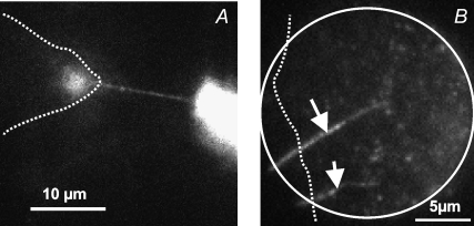
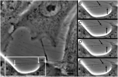
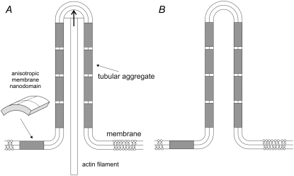
Communication between cells is crucial for proper functioning of multicellular organisms. The recently discovered membranous tubes, named tunneling nanotubes, that directly bridge neighboring cells may offer a very specific and effective way of intercellular communication. Our experiments on RT4 and T24 urothelial cell lines show that nanotubes that bridge neighboring cells can be divided into two types. The nanotubes of type I are shorter and more dynamic than those of type II, and they contain actin filaments. They are formed when cells explore their surroundings to make contact with another cell. The nanotubes of type II are longer and more stable than type I, and they have cytokeratin filaments. They are formed when two already connected cells start to move apart. On the nanotubes of both types, small vesicles were found as an integral part of the nanotubes (that is, dilatations of the nanotubes). The dilatations of type II nanotubes do not move along the nanotubes, whereas the nanotubes of type I frequently have dilatations (gondolas) that move along the nanotubes in both directions. A possible model of formation and mechanical stability of nanotubes that bridge two neighboring cells is discussed.


Figures

FIGURE 1
FIGURE 1
Movement of a small phospholipid prolate traveling vesicle (white arrow) along a thin phospholipid tube (black arrow) attached to a spherical liposome (adapted from the study by Iglič et al. (7)). In the final stage, the vesicle was fused with the membrane of liposome.
FIGURE 2
FIGURE 2
Type I nanotubes. A is a phase contrast image of live T24 cells, whereas B is a fluorescence micrograph showing actin labeling of the same cells as in A after 15 min of paraformaldehyde fixation. Cell C1 is approaching the cells C2 and C3 (see Movie S1). The white arrows in A and B indicate short and dynamic membrane protrusion with which the approaching cell explores its surroundings. The black arrow in A points at protrusions that have already connected to the target cell. In all these multiple tubular connections, actin filaments are present (arrows in B). Bridging nanotubes of type I can be more than 20 μm in length and occasionally bifurcations are seen (arrow in C).
FIGURE 3
FIGURE 3
The stable membrane protrusions after cytochalasin D treatment of T24 cells can be seen by time-lapse phase-contrast microscopy. After incubation in cytochalasin D for 30 min, a time-lapse sequence with Axio-Imager Z1 microscope (Carl Zeiss) was recorded (see Movie S2). The white arrows point to the tip of two nanotubes that move passively. Times indicated in A through F are the times passed from the beginning of the time-lapse sequence.
FIGURE 4
FIGURE 4
A transmission electron micrograph showing an anchoring type of intercellular junction (arrow) connecting a nanotubule to the protrusion of a neighboring cell.
FIGURE 5
FIGURE 5
Exchange of actin-GFP via a bridging nanotube between two T24 cells. Stable, actin-GFP transfected T24 cells were frequently found to be interconnected by TNTs. Occasionally, connections were observed between a high expressing cell and a cell devoid of actin-GFP (cell borders are indicated by a dashed line). (A) The spreading of actin GFP into the second cell is clearly visible as a cone of fluorescence growing into a GFP-actin negative cell. (B) Two nanotubes indicated by arrows connect the shown nontransfected cell with an actin-GFP positive cell outside the imaged area (the imaging pinhole is indicated by a full line). Multiple diffraction-limited spots could be observed at high mobility, indicating the presence of free actin-GFP molecules in the nontransfected cell (see Movie S3).
FIGURE 6
FIGURE 6
Urothelial cells T24 labeled with lipophilic stain DiI were cocultured with unlabeled T24 cells. The nanotubes (arrow) of stained cells (red) became protruded and attached to unstained cells (green) in 3 h. However, even after 24 h, the DiI stain did not spread to the connected cells.
FIGURE 7
FIGURE 7
In urothelial cell line T24, a long tubular structure connects cells of the two cell clusters C1 and C2 (A). B is a magnified region of the area in the black frame in A. Such long, singular tubes of type II contain thin cytokeratin filaments (arrow in C). In C, cytokeratin 7 is labeled in red, actin in green, and the nucleus with DAPI in blue.
FIGURE 8
FIGURE 8
Two separating T24 cells (C1 and C2) having actin (A) and cytokeratin (B) filaments present in the forming protrusions. Membranes of the two cells detach at certain sites, forming tail-like protrusions between the membranes. The membranes gradually separate as the cells move apart, pulling and dividing their cytoskeletal content. Note that both actin (A) and cytokeratin (B) filaments are still present in growing tubular connections.
FIGURE 9
FIGURE 9
Membrane nanotubes with gondolas (arrows) observed between cells in the human urothelial cell line RT4 (A) and T24 (B and C) by scanning electron microscopy under physiological conditions. Note that the gondolas are an integral part of the tubes.
FIGURE 10
FIGURE 10
Movement of small vesicles along membrane bridging nanotubes connecting two locations (white arrows in A) on the membrane surface of cells in the human urothelial cell line RT4 observed by phase contrast microscopy in cell culture under physiological conditions. Black arrows point to two carrier vesicles (gondolas) that moved in opposite directions (BE).
FIGURE 11
FIGURE 11
Fusion of a gondola (arrows) with a cell body is seen after a time-lapse sequence showing directional movement of the gondola along a nanotube. The time sequence in seconds is indicated on the upper left side of each micrograph.
FIGURE 12
FIGURE 12
Schematic figure of three different kinds of intrinsic shapes of flexible membrane nanodomains: partly cylindrical, flat, and saddle-like. The intrinsic shape of the nanodomain can be characterized by two intrinsic (spontaneous) principal curvatures C1m and C2m. When C1m = C2m, the nanodomain is isotropic, whereas if C1m ≠ C2m, the nanodomain is anisotropic (12). Bending deformation and rotation of the nanodomain allow the nanodomain to adapt its shape and orientation to the actual membrane curvature, which in turn is influenced by the nanodomain. The nanodomains with C1m > 0 and C2m formula image 0 favor cylindrical geometry of the membrane. Nanodomains with C1m = C2m = 0 prefer flat membrane shape, whereas nanodomans with C1m > 0 and C2m < 0 favor saddle-like membrane geometry (as, for example, in the membrane neck connecting the daughter vesicle to the parent membrane).
FIGURE 13
FIGURE 13
Schematic illustration of stabilization of type I nanotubular membrane protrusions by accumulation of anisotropic membrane nanodomains in the tubular region. Growing actin filaments push the membrane outward (A). The protrusion is additionally stabilized by accumulated anisotropic nanodomains with C1m > 0 and C2m formula image 0 (see Fig. 12) that favor anisotropic cylindrical geometry of the membrane (12,30). Possible candidates for such anisotropic membrane nanodomains might be prominin-containing nanodomains (24,25,28). The cylindrical-shaped anisotropic membrane domains, once assembled in the membrane region of a nanotubular membrane protrusion, keep the protrusion mechanically stable even if the cytoskeletal components (actin filaments) are disintegrated by cytochalasin D (B).
FIGURE 14
FIGURE 14
Schematic illustration of nanotubule-directed transport of small carrier vesicles (gondolas) transporting granular content and membrane particles.

References

    1. Linder, M. E., and A. G. Gilman. 1992. G-proteins. Sci. Am. 267:36–43. - PubMed
    1. Kumar, N. M., and N. B. Gilula. 1996. The gap junction communication channel. Cell. 84:381–388. - PubMed
    1. Mathivet, L., S. Cribier, and P. F. Devaux. 1996. Shape change and physical properties of giant phospholipids vesicles prepared in the presence of an AC electric field. Biophys. J. 70:1112–1121. - PMC - PubMed
    1. Kralj-Iglič, V., G. Gomiscek, J. Majhenc, V. Arrigler, and S. Svetina. 2001. Myelin-like protrusions of giant phospholipid vesicles prepared by electroformation. Colloids Surf. A. 181:315–318.
    1. Kralj-Iglič, V., A. Iglič, G. Gomišček, V. Arrigler, and H. Hägerstrand. 2002. Microtubes and nanotubes of phospholipid bilayer vesicles. J. Phys. Math. Gen. 35:1533–1549.

Publication types

LinkOut - more resources